Skip to content

Fundamentals & Technology

What Is a DC Isolator Switch and How Does It Work?

A practical introduction to DC isolator switches in solar PV systems, including terminology, operating principle, system positions, device boundaries, and the evidence needed before specification.
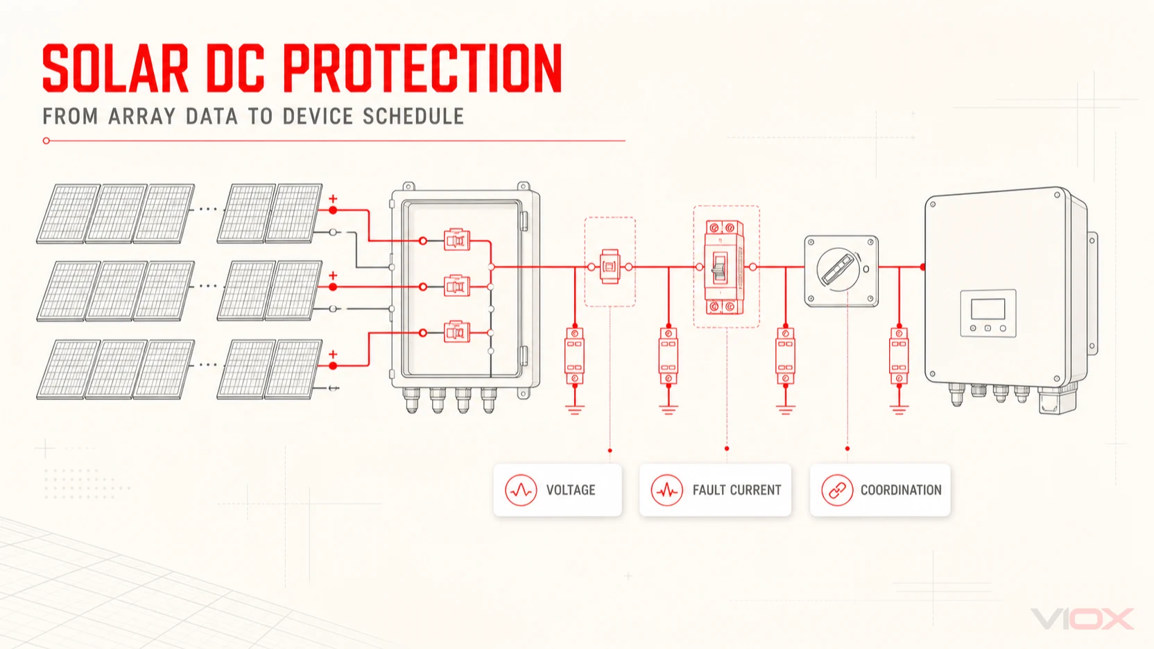
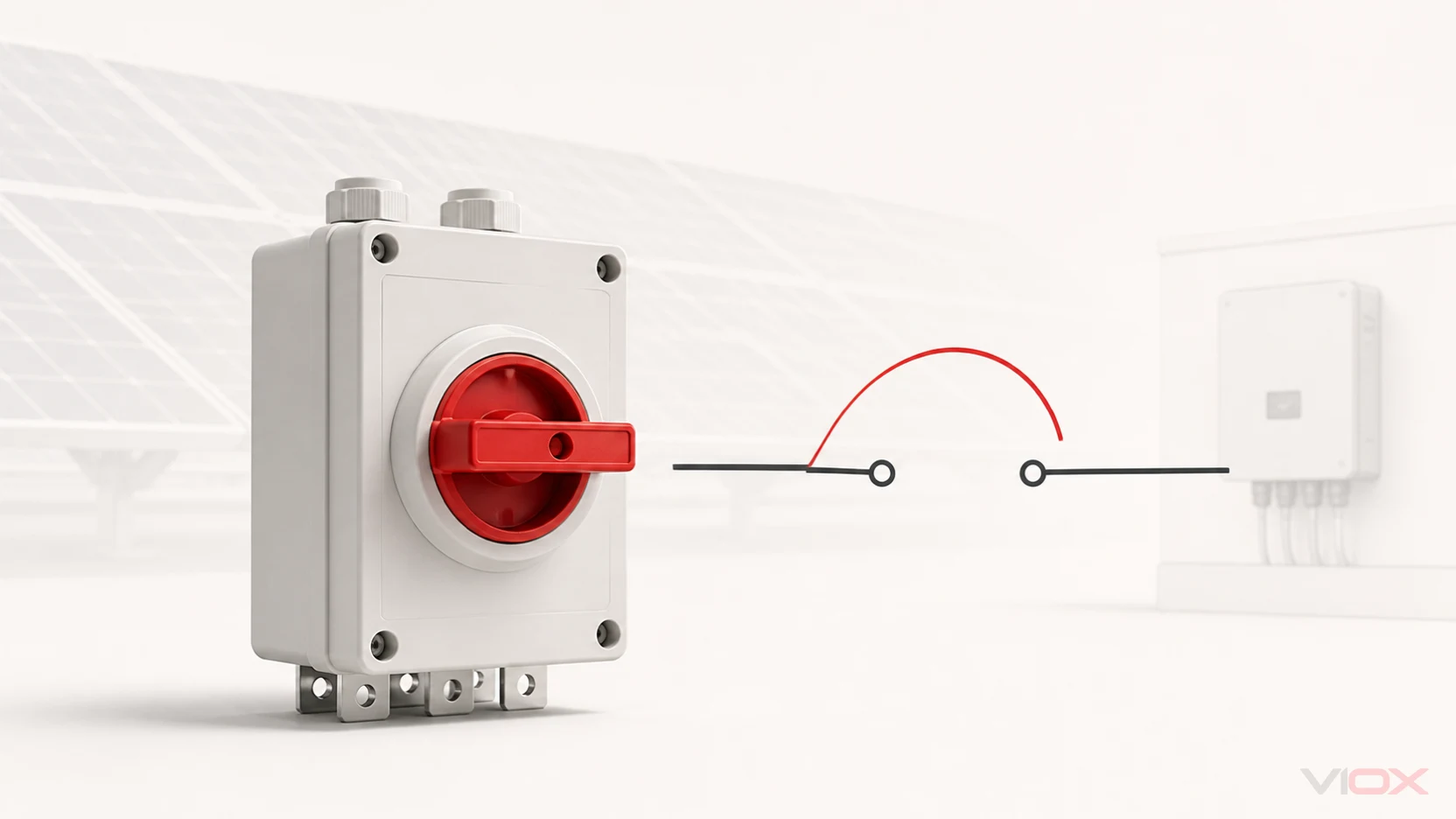
Rotary DC switch-disconnector defining an isolation boundary in a solar PV circuit
VIOX / TECHNICAL ARTICLE
On this page

A DC isolator switch is a manually operated device that creates a defined disconnection point in a direct-current circuit. In solar photovoltaic systems, the term commonly refers to a DC-rated switch-disconnector: a device that can make and break current within its documented utilization category and also provide an isolation function. The name alone is not enough—its markings, ratings, wiring arrangement, and manufacturer instructions determine what the device may safely do.

This distinction matters because a PV array can remain a source of DC voltage whenever light reaches the modules. Moving one handle to OFF isolates only the conductors and equipment inside the switch's designed boundary; it does not prove that the entire PV installation is de-energized.

Safety boundary: This article explains functions and terminology, not an installation or live-switching procedure. PV DC work should be designed, installed, isolated, tested, and maintained by qualified personnel under the applicable rules and controlled product instructions.

DC isolator, disconnector, and switch-disconnector: what do the names mean?

In everyday solar language, DC isolator, DC disconnect, and DC isolator switch are often used for the same product class. Technical documentation can be more precise.

TermCore functionImportant boundary
Disconnector or isolatorProvides isolation when open and used within its documented conditionsA pure disconnector is not automatically intended to make or break normal load current
SwitchMakes, carries, and breaks current under its specified operating conditionsIt is not automatically suitable for isolation
Switch-disconnectorCombines a switching function with a disconnector's isolation functionIts DC utilization category, voltage, current, and circuit arrangement still control the permitted duty
DC isolator switchCommon market term, especially in solar PVVerify whether the actual device is declared as a DC switch-disconnector rather than relying on the market name

IEC 60947-3:2020 covers switches, disconnectors, switch-disconnectors, and fuse-combination units within its stated scope up to 1,500 V DC. A 2025 amendment is also available in the current consolidated edition. Citing that standard family describes a product scope; it does not prove that a particular device, rating, or installation is compliant.

For a specification, the useful question is therefore not simply “Is this an isolator?” It is: Which switching and isolation functions are declared for this exact product and circuit configuration?

Why DC switching needs a purpose-designed device

Alternating current passes through a natural current zero during every cycle. Direct current does not. When contacts open under DC load, an arc can persist unless the switching mechanism, contact separation, pole arrangement, and arc-control features are designed for the stated duty.

A purpose-designed DC switch-disconnector manages that event through a coordinated mechanism. Depending on the product, this may include fast stored-energy operation, multiple contacts in series, defined contact travel, arc chambers, magnetic influence, or a prescribed pole connection. Those details are product-specific; they should not be inferred from an AC switch that happens to carry a similar current number.

Three ratings that look similar can describe different limits:

  • Rated operational voltage relates to the circuit and declared switching duty.
  • Rated operational current is tied to the voltage, utilization category, pole arrangement, and operating conditions.
  • Rated insulation voltage is an insulation-system reference and is not, by itself, permission to switch that voltage under load.

That is why a prominent “1,500 V” marking or catalog headline cannot replace the arrangement-specific operating table and wiring diagram.

Where a DC isolator switch sits in a solar PV system

A DC isolation point defines a service or equipment boundary. Depending on the system architecture and applicable rules, a switch-disconnector may be associated with a string group, a PV combiner box, an inverter DC input, or DC distribution equipment.
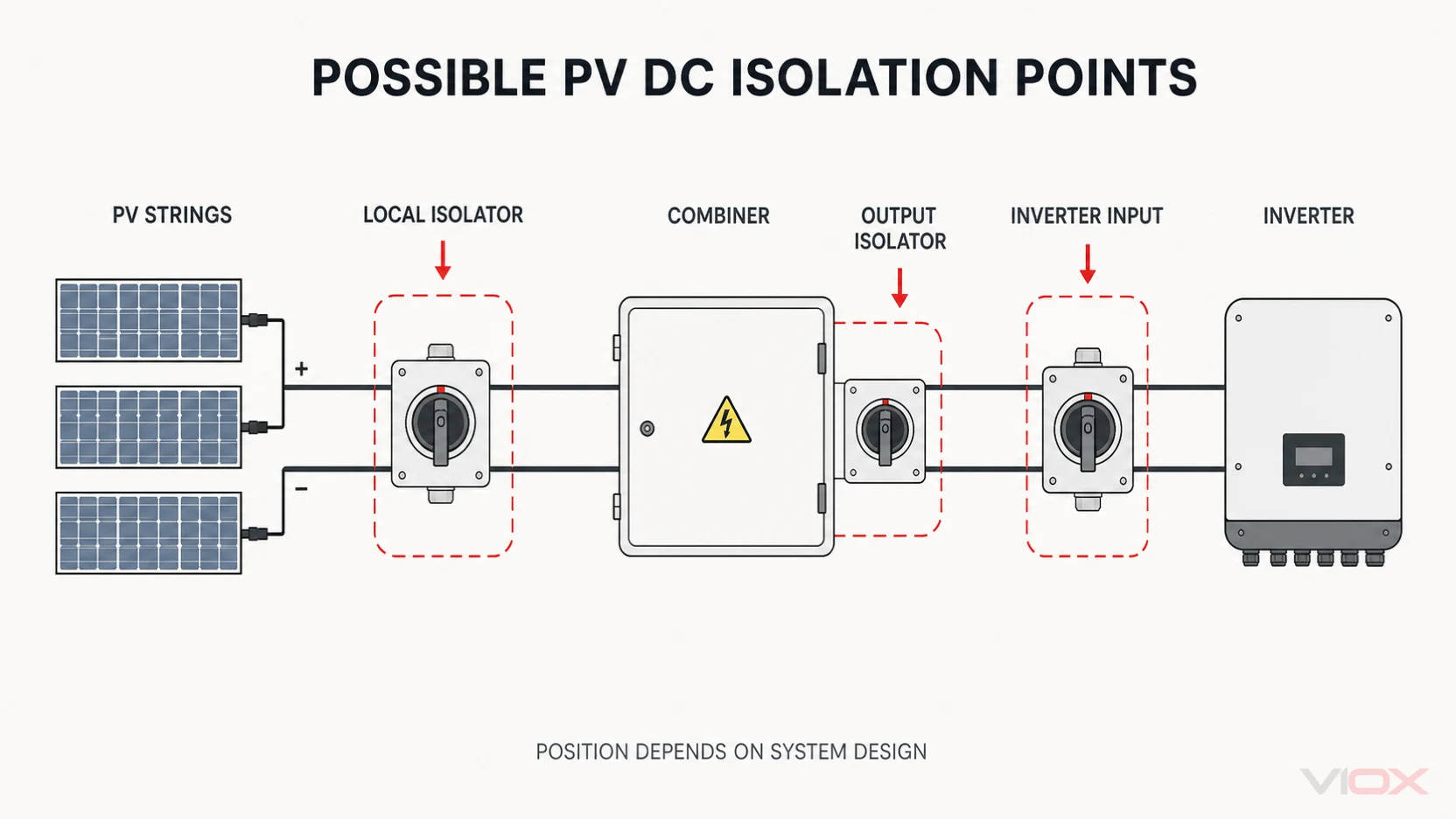
Conceptual positions for DC isolator switches between PV strings, a combiner, and an inverter

A simplified power path may look like this:

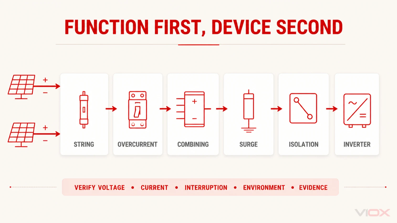
PV strings → combining and protection → DC isolation point → inverter or other power-conversion equipment

This is a functional map, not a universal wiring diagram. Real projects can include multiple maximum-power-point-tracker inputs, distributed electronics, more than one source, battery circuits, integrated inverter disconnects, or market-specific shutdown equipment. The designer must identify every source and decide which conductors and equipment each isolation point actually separates.

The current IEC 62548-1 PV-array design standard includes DC wiring, electrical protection devices, switching, and earthing provisions within its scope. Its 2025 consolidated version includes revised isolation provisions. IEC 60364-7-712:2025 addresses PV electrical installations. The adopted edition, national implementation, project design, and authority requirements must all be confirmed rather than assumed from an international-standard title.

How a rotary DC switch-disconnector works

Many solar DC isolators use a rotary handle connected to a fast switching mechanism. The handle provides the user interface, while an internal stored-energy mechanism moves the contacts quickly rather than allowing contact speed to depend entirely on how slowly the operator turns the handle.

At a conceptual level, operation has four stages:

  1. ON state: the specified poles carry current through closed contacts.
  2. Operating input: the handle drives or releases the switching mechanism.
  3. Rapid contact movement: contacts separate, and the device controls the arc within its documented DC duty.
  4. OFF state: the contacts reach the declared open position and provide the intended isolation function.

The mechanism does not make every operating situation safe. A device can be incorrectly rated, incorrectly connected, exposed beyond its enclosure limits, or used in a circuit with energy and fault conditions outside its evidence. Isolation also needs verification under the site's safe-working procedure; handle position alone is not a test result.

What a DC isolator does—and does not do

The clearest way to avoid specification errors is to assign one primary function to each device before comparing products.
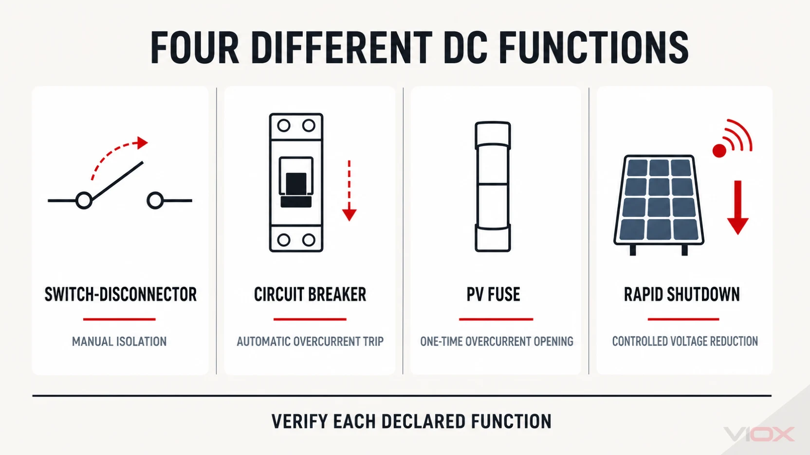
Comparison of DC switch-disconnector, circuit breaker, PV fuse, and rapid-shutdown functions
DevicePrimary roleTypical actionWhat it does not automatically provide
DC switch-disconnectorIntentional switching and isolation within declared ratingsManual operationAutomatic overload or short-circuit interruption
DC circuit breakerAutomatic overcurrent interruption within its trip and breaking ratingsTrips on defined overcurrent conditions; may also be manually operatedIsolation or load switching unless those functions are explicitly declared
PV fuseOne-time overcurrent interruption within its documented PV dutyFuse element opens under qualifying overcurrentRoutine switching, reset, surge protection, or a visible service control
Rapid-shutdown equipmentReduces voltage within a defined array boundary when initiated under the applicable system rulesControlled system responseA universal substitute for mechanical isolation or overcurrent protection

DC isolator vs DC circuit breaker

A DC isolator is selected primarily for intentional switching and isolation. A DC circuit breaker is selected primarily for automatic overcurrent protection and fault interruption. Some breakers are also marked and documented for switching or isolation, but that capability must be verified rather than assumed.

The reverse is equally important: a switch-disconnector may have a short-time withstand or conditional short-circuit rating, yet that does not turn it into an automatic protective device. It normally relies on coordinated upstream or downstream protection for fault clearing.

DC isolator vs PV fuse

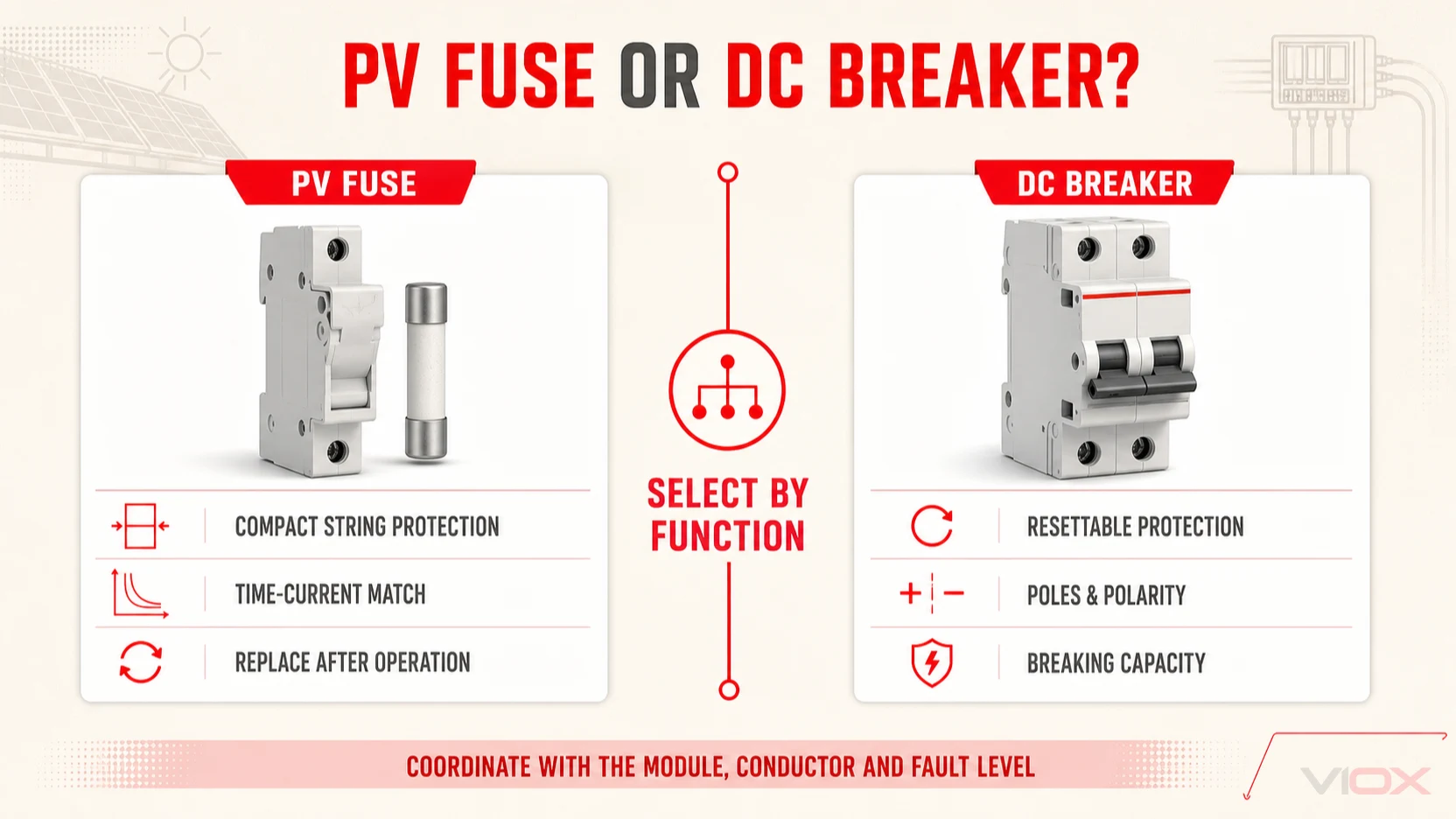
A PV DC fuse responds once to qualifying overcurrent and must then be replaced. An isolator gives an operator a repeatable control point. One function does not imply the other, although both may appear in the same combiner box or DC assembly.

DC isolator vs rapid shutdown

Rapid shutdown is a system-level function defined by the applicable market rules and equipment architecture. It can reduce voltage within a specified boundary after initiation, but it should not be described as making every conductor in sunlight dead. A local mechanical isolator and a rapid-shutdown system can therefore serve different boundaries.

For a broader device-coordination workflow, use the solar DC circuit-protection guide.

Which specifications define the application boundary?

This Hub does not replace a project selection calculation, but it should make the evidence request more precise. At minimum, review these categories together:

Evidence categoryWhat to verifyWhy it matters
Circuit voltageMaximum corrected DC voltage and the exact product's operational ratingLow temperature can increase PV open-circuit voltage; insulation voltage alone is insufficient
Current and switching dutyCorrected operating current, declared utilization category, and expected operating dutyA thermal current number does not describe every load-breaking condition
Poles and circuit arrangementRequired live conductors, number of poles, series connections, polarity conditions, and approved diagramVoltage and current ratings can change with the pole arrangement
Fault coordinationWithstand or conditional short-circuit data and the specified protective deviceAn isolator normally does not clear overcurrent automatically
Installation formatPanel, DIN-rail, enclosed, or door-coupled arrangementThe format changes access, enclosure integration, and operating interface
EnvironmentAmbient temperature, enclosure ingress protection, UV/corrosion conditions, pollution degree, and mounting constraintsOutdoor enclosure suitability cannot be inferred from the internal switch alone
Human interfacePosition indication, lockability, accessibility, labeling, and operating instructionsA clear service boundary depends on both device evidence and installation design
Controlled documentsDatasheet, wiring diagram, declaration or certificate where required, installation instructions, and exact order codeMarketing descriptions do not control the final configuration

These checks are interdependent. For example, an operating-current value may apply only at one voltage and one pole configuration. An IP rating may apply only to an enclosed version, not to a bare panel-mounted switch. A declaration for one order code should not be generalized to every member of a family.

Common specification mistakes

Treating the handle as proof of complete de-energization

OFF describes the switch state. It does not identify every possible source or prove absence of voltage. PV modules can remain energized in light, and parallel sources or stored energy may exist elsewhere in the system.

Using an AC isolator because the current rating looks adequate

DC arc interruption and pole configuration require DC-specific evidence. Comparable front-panel dimensions or current markings do not establish equivalent switching performance.

Reading a series maximum as a universal rating

Voltage, current, utilization category, poles, and wiring arrangement form one rating set. Separating the largest number from that set creates a misleading specification.

Assuming an isolator replaces protection

Isolation, overcurrent protection, surge protection, arc-fault response, and rapid shutdown are different functions. A project may combine several of them, but only where the system design and product documentation support the combination.

Treating one component standard as approval of the installation

IEC 60947-3 addresses equipment within its scope. PV array design and installation sit in other document layers, and destination markets can require national adoption, certification, or additional rules. Evidence must match the product, assembly, and installation layer being claimed.

VIOX VOD1 DC isolator switch family

The VIOX DC isolator switch family includes the VOD1 platform for photovoltaic circuits. The current family information lists panel mounting, 35 mm DIN-rail mounting, enclosed, and door-clutch formats, along with A2, A4, 4T, 4B, and 4S circuit arrangements.

Published family references include 1,500 V DC/25 A and 1,200 V DC/45 A operating combinations, but these values are not interchangeable. The applicable current depends on the operating voltage and pole arrangement. The enclosed configuration is described with IP66 protection; that statement should not be transferred to an unenclosed device or to the completed installation without the relevant evidence.

For an initial VOD1 inquiry, provide the circuit voltage and current basis, required pole arrangement, installation format, environmental conditions, destination market, and requested controlled documents. VIOX can then relate the requirement to a specific configuration and order code. Contact sales@vioxsolar.com for a documented product review.

A practical one-sentence specification boundary

A defensible starting statement is: Provide a DC switch-disconnector whose exact order code, operational voltage and current, utilization category, pole arrangement, fault coordination, enclosure, and documentation are suitable for the identified PV isolation boundary and destination market.

That sentence does not complete the design. It prevents the most common category error: buying a device by the words “DC isolator” and one headline rating while leaving the actual switching duty and circuit arrangement undefined.
Fundamentals & Technology

DC Fuse Guide for Solar PV Systems: Types, Ratings, and Applications

A practical orientation to PV DC fuses, including reverse-current protection, gPV terminology, fuse-link and holder coordination, key ratings, standards boundaries, and verified VIOX product routes.
PV DC fuse guide cover showing a cylindrical fuse-link and DIN-rail fuseholder in a solar application
VIOX / TECHNICAL ARTICLE
On this page

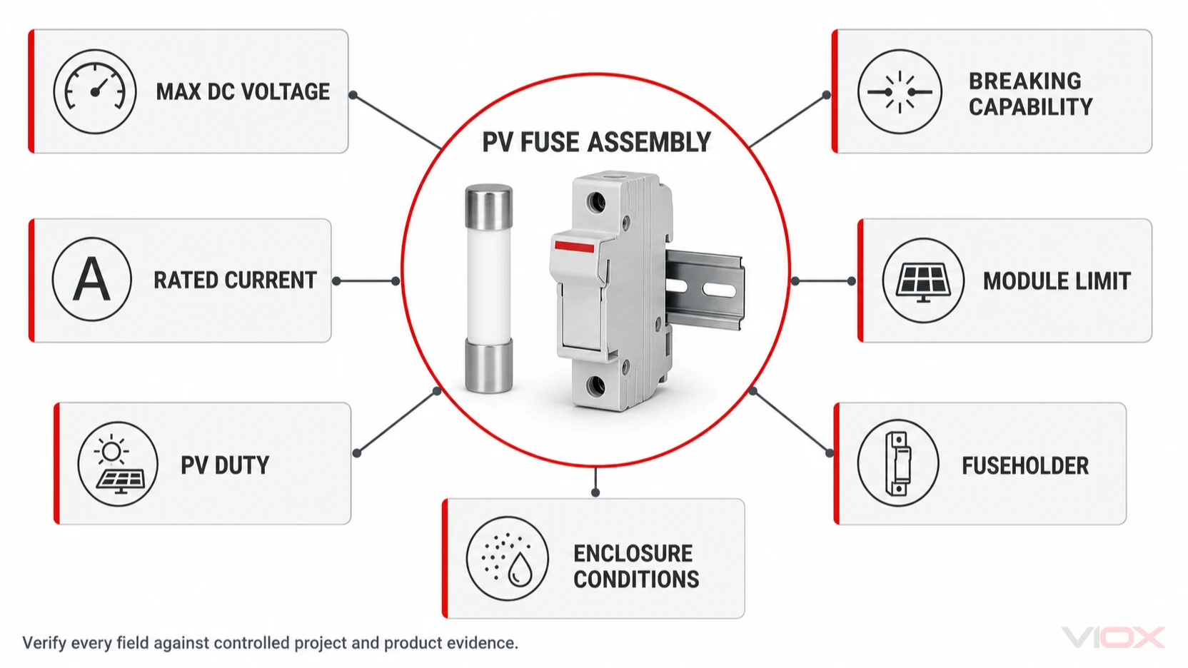
A photovoltaic (PV) DC fuse is a one-time overcurrent protective device used where reverse current or another available DC source could exceed the safe limit of a PV string, conductor, module, or coordinated component. It is not selected from current alone. A defensible specification also checks maximum circuit voltage, PV fuse duty, breaking capability, module limits, time-current behavior, the matching fuseholder, and the conditions inside the enclosure.

This guide maps those decisions and shows where to continue. It focuses on PV-array DC circuits. Battery-bank, electric-vehicle, semiconductor, automotive, and general AC fuse design are outside its boundary.

Where a PV DC Fuse Sits in the System

In a simple PV string with no other source capable of feeding a damaging current into a fault, a fuse may add no useful overcurrent protection. The design question changes when strings are connected in parallel or when another source can feed the circuit.

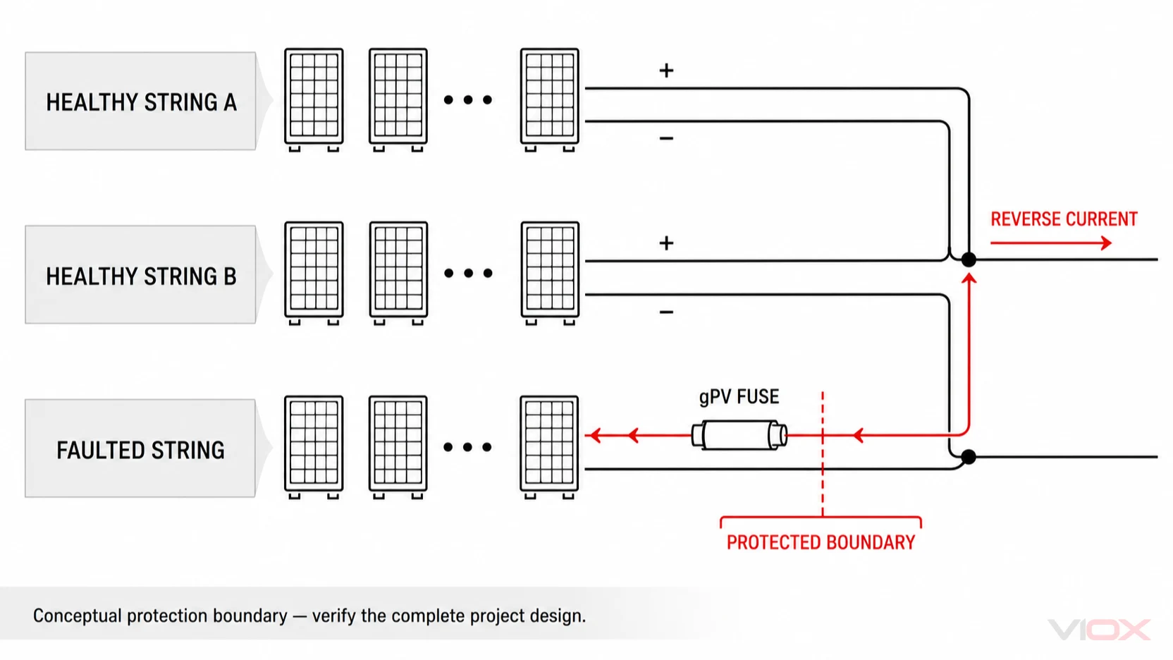
If one parallel string develops a fault, healthy strings may feed reverse current toward that string. A string fuse is positioned so it can interrupt that contribution before the protected module, string conductor, or another coordinated component is exposed beyond its permitted limit. The relevant source is therefore not only the current produced by the faulted string; it is the current available from the rest of the architecture.

Conceptual reverse-current path from healthy PV strings toward a faulted string through a gPV fuse boundary

Common PV fuse positions include:

  • individual string inputs before or inside a PV combiner box;
  • array or subarray circuits where several combined sources create a higher available current;
  • coordinated protection points inside equipment designed and documented for PV DC service.

The fuse protects a defined electrical boundary. It does not automatically provide load-break switching, visible isolation, surge limitation, or arc-fault detection. Start with the complete source and device architecture described in How to Select Circuit Protection for a Solar DC System, then assign the fuse only the overcurrent function it is expected to perform.

These terms are related but not interchangeable.

TermMeaning in this guideBoundary to remember
DC fuseA fuse intended and rated to interrupt specified direct-current conditions“DC” alone does not establish suitability for PV string protection
PV fuseA fuse designed for photovoltaic circuit duty under the applicable product frameworkVerify the exact marking, voltage, current, breaking capability, and documentation
gPV fuse-linkThe replaceable fuse-link associated with full-range PV protection under the IEC 60269-6 frameworkThe marking belongs to a defined fuse-link duty; it is not a generic label for every DC fuse
FuseholderThe component that accepts and connects the fuse-linkHolder voltage, current, thermal behavior, terminals, touch protection, and format must coordinate with the link
Fuse assemblyThe working combination of fuse-link, holder, conductors, terminals, enclosure, and service conditionsA suitable link cannot compensate for an unsuitable holder or overheated termination

The replaceable element is the fuse-link. The fuseholder provides the mechanical and electrical interface. Procurement and design records should identify both, because changing the holder, link format, terminal arrangement, or enclosure temperature can change the behavior of the installed protection point.

How a PV Fuse Operates

A fuse-link contains an element that heats as current flows. When the current and duration reach the link's operating characteristic, the element melts and the fuse interrupts the circuit within its rated capability. The result is a permanent open state: unlike a circuit breaker, the fuse cannot be reset.

That one-time operation has an important maintenance consequence. Replacing an open fuse without investigating the cause can restore the same fault path. The service process should establish why the fuse operated and inspect the associated holder, terminals, conductors, polarity, affected string, and coordinated components under the site's approved safe-work procedure. This article does not provide an energized testing or replacement procedure.

Fuse operation also depends on more than the number printed in amperes. Time-current behavior, cyclic PV loading, enclosure temperature, contact resistance, holder condition, and the available reverse or fault current all affect the real protection outcome. Those variables belong in the engineering record, not in an assumed universal rule.

PV DC Fuse Types and Physical Formats

PV protection uses fuse-links and holders in several physical arrangements. For the current VIOX Solar family, the relevant cylindrical formats are:

  • 10 × 38 mm, used by the RT18-32 / VOPV-32 platform;
  • 14 × 51 mm, used by the RT18-63 / VOPV-63 platform.

The physical size is an interface, not a complete specification. Two links that fit the same nominal format should not be treated as interchangeable until their PV/DC duty, voltage, current, breaking capability, time-current data, dimensions, holder compatibility, and controlled documentation have been compared.

This distinction is particularly important when a product family can also serve other low-voltage circuits. A general-purpose fuse-link, an AC fuse, and a PV-rated fuse-link may share a familiar shape while having different application evidence.

The Ratings That Define a PV Fuse Application

The following map separates the main specification fields and the evidence needed to close each one.

PV fuse specification map for voltage, current, PV duty, breaking capability, module, holder, and enclosure evidence
Specification fieldWhy it mattersWhat must be verified
Maximum DC voltageThe fuse must interrupt at the highest credible circuit voltage, not only nominal operating voltageCorrected maximum string open-circuit voltage, circuit topology, polarity arrangement, and exact link/holder DC rating
Rated currentThe link must carry expected PV current without unwanted operation while remaining within the protected equipment limitsModule current data, design factors, environmental conditions, conductor limits, and available standard ratings
PV utilization dutyPV strings can present sustained, relatively low fault-current conditions compared with many conventional circuitsApplicable gPV or other documented PV duty for the exact product and market
Breaking capabilityThe fuse must interrupt the available DC current under the specified voltage and circuit conditionsDeclared breaking rating and the maximum available reverse/fault current at that location
Time-current characteristicOperating time determines whether the fuse protects the intended component without unnecessary openingManufacturer curve, tolerance, cyclic loading, inrush or transient behavior where relevant, and coordination study
Module maximum series-fuse ratingThe module manufacturer defines a key coordination boundaryExact controlled module datasheet and approved project module reference
Conductor coordinationThe protected conductor must remain within its applicable thermal limitCable type, cross-section, installation method, temperature, grouping, and applicable design rules
Fuse-link formatThe link must fit and connect correctly10 × 38, 14 × 51, or another exact dimensional system and contact arrangement
Fuseholder ratingThe holder carries current continuously and contains the interruption eventDC voltage, current, accepted link, terminal range, tightening data, touch protection, and temperature behavior
Enclosure conditionsHeat, ingress, contamination, altitude, and terminal resistance can change performanceAssembly temperature rise, enclosure rating, ventilation, mounting, altitude, maintenance access, and manufacturer limits

The circuit voltage must be compared with the complete fuse assembly rating. Likewise, the module maximum series-fuse rating is not a recommendation to install that exact ampere value; it is an upper coordination boundary that must be considered together with operating current, reverse-current exposure, conductor protection, and available fuse characteristics.

How to Decide Whether a PV String Needs a Fuse

There is no reliable universal answer based only on a phrase such as “three strings require fuses.” The number of parallel strings can influence reverse-current exposure, but the final decision depends on the electrical behavior and limits of the actual system.

Use this sequence at orientation level:

  1. Draw every source path. Identify the PV strings, combining points, inverter inputs, DC conditioning equipment, and any other source that can feed the circuit.
  2. Identify the faulted boundary. Define the string, conductor, module, or component that the protective device would protect.
  3. Determine the available reverse or fault current. Account for the healthy parallel sources and the operating assumptions required by the applicable design method.
  4. Check the controlled module data. Record short-circuit current, relevant coefficients, and maximum series-fuse rating from the exact module datasheet.
  5. Check the conductor and assembly. Include cable installation, holder, terminals, enclosure temperature, and coordination with upstream and downstream devices.
  6. Apply the target-market rules. IEC-based, NEC-based, and other national frameworks must not be blended into one formula.
  7. Produce a complete specification. State the fuse-link duty, voltage, current, breaking capability, format, holder, environmental conditions, and required evidence.

This process determines whether protection is needed before it determines a catalog number. A future detailed selection guide can take the verified project inputs through the rating and RFQ workflow; this Hub deliberately stops at the decision map.

PV Fuse vs. DC Breaker, Isolator, and SPD

Solar DC devices are sometimes grouped together because they appear in the same combiner box or inverter-side assembly. Their functions remain different.

DevicePrimary functionWhat it does not automatically provide
PV fuseOne-time overcurrent interruption within its documented PV/DC dutyResetting, routine switching, visible isolation, surge limitation
DC circuit breakerAutomatic overcurrent interruption with a resettable mechanism when correctly rated and appliedEvery breaker is not automatically a load-break isolator or suitable for every PV topology
DC switch-disconnectorIntentional switching and isolation within its documented utilization categoryOvercurrent protection unless the assembly explicitly includes and coordinates it
PV DC SPDLimits transient overvoltage by diverting surge currentSustained overcurrent protection, switching, or isolation

A fuse and breaker should not be compared as if one is universally superior. The source behavior, interruption duty, switching need, maintenance strategy, coordination objective, available fault current, and product evidence determine the fit. For breaker-specific orientation, use the DC MCB Guide for Solar PV Systems.

Standards and Evidence Boundaries

Standards answer different questions. A standard named in a specification does not by itself prove that a particular product, holder, or assembled enclosure complies.

  • IEC 60269-1 provides general requirements for low-voltage fuses.
  • IEC 60269-6 adds supplementary requirements for fuse-links used to protect solar PV energy systems. Its published scope covers PV strings and arrays in circuits up to 1,500 V DC.
  • IEC TR 60269-5 provides application guidance for low-voltage fuses and includes PV protection guidance.
  • IEC 62548-1 addresses PV-array design requirements, including DC wiring and electrical protection devices.
  • UL 248-19 is identified by UL Solutions for photovoltaic fuses in North American product evaluation.
  • UL 4248-19 is identified by UL Solutions for photovoltaic fuseholders.

The 1,500 V boundary in IEC 60269-6 is a standards-scope statement, not a VIOX product rating. The current VIOX PV DC Fuse family page states 1,000 V DC. A project requiring another voltage or a named certification needs exact controlled product documentation rather than an inference from the standard title.

Installation rules also depend on the target market and project. Record the applicable code or design standard separately from the fuse-link product standard, holder evidence, module datasheet, and assembly verification.

VIOX PV DC Fuse Product Family

VIOX Solar currently presents two DIN-rail PV DC fuse platforms. The values below are product-family orientation data from the current Payload product record; the controlled datasheet and approved quotation define the supplied configuration.

VIOX platformFuse-link formatPublished family boundaryProduct route
RT18-32 / VOPV-3210 × 38 mmPart of the 1–50 A, model-dependent family at 1,000 V DCReview RT18-32 / VOPV-32
RT18-63 / VOPV-6314 × 51 mmPart of the 1–50 A, model-dependent family at 1,000 V DCReview RT18-63 / VOPV-63

Both platforms are presented within the VIOX PV DC Fuse product family, which lists TH35 / 35 mm DIN-rail mounting. Do not infer a specific breaking capacity, certification, curve, or model current from this overview; request the exact controlled reference for the required configuration.

Choose Your Next DC Fuse Resource

Use the next page that matches the work in front of you:

For model confirmation, send the project maximum DC voltage, exact module datasheet, string arrangement, current inputs, required fuse-link format, holder and enclosure conditions, target market, and requested documentation to sales@vioxsolar.com.

Sources

Fundamentals & Technology

DC MCB Guide for Solar PV Systems: Types, Ratings, and Applications

A practical orientation to DC miniature circuit breakers in solar PV systems, including application boundaries, voltage and current ratings, breaking capacity, pole arrangements, standards scope, and verified VIOX product families.
DC miniature circuit breaker for solar photovoltaic protection with rooftop solar panels
VIOX / TECHNICAL ARTICLE
On this page

A DC MCB is a miniature circuit breaker designed to interrupt direct-current overloads and short circuits within its documented voltage, current, fault-level, polarity, and installation limits. In a solar photovoltaic system, the appropriate device depends on the actual circuit and the manufacturer's instructions. A DC MCB does not automatically replace a PV fuse, switch-disconnector, surge protective device, or complete protection design.

For engineers, installers, and procurement teams, the practical starting point is to identify where the breaker sits, what electrical conditions it must withstand, and which adjacent protection functions belong to other devices. This guide maps those decisions without turning a general overview into an installation procedure.

What Is a DC MCB?

MCB stands for miniature circuit breaker. A DC MCB is a compact protective device explicitly designed and rated for direct-current circuits, usually fitted within a distribution assembly, combiner enclosure, or comparable equipment arrangement.

Its central protection functions are distinct:

  • Overload protection responds to sustained current above the device's applicable operating conditions.
  • Short-circuit protection responds to a fault capable of producing a current that the breaker must interrupt safely.

Neither function can be established from physical appearance alone. The product's DC voltage rating, current rating, breaking capacity, pole arrangement, polarity restrictions, and installation instructions determine whether a particular breaker suits a particular circuit.

The word “miniature” describes a product class and format. It does not mean the breaker can safely interrupt every DC source, nor does a larger ampere number make an unsuitable voltage rating acceptable.

Why Solar PV Systems Need DC-Rated Circuit Breakers

Direct current creates a different interruption challenge from alternating current. An AC waveform regularly passes through zero; a DC current does not provide that natural current-zero transition. When breaker contacts open under load or fault, the resulting arc therefore needs a contact system and extinguishing arrangement suitable for the actual DC application.

Consequently, a breaker marked for an AC voltage cannot be assumed suitable for the same DC voltage. A product can carry both AC and DC ratings, but the DC rating must be explicit and must apply to the selected configuration.

Solar modules add another complication: string voltage changes with operating conditions. Designers assess the array's maximum expected voltage using the project's applicable calculation method, the module's open-circuit voltage data, temperature coefficient, and minimum design temperature. The selected breaker's relevant DC rating must accommodate that project result.

No single multiplier, pole arrangement, or nominal system label resolves this check for every jurisdiction. The module documentation, adopted installation rules, project design, and device instructions all matter.

Where DC MCBs Are Used in a Solar Power System

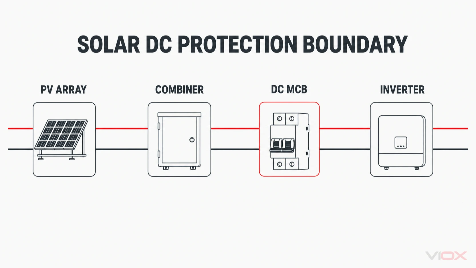
A photovoltaic installation can include several distinct DC circuit locations. The fact that a breaker is suitable for one location does not establish suitability for every other location.

Conceptual solar DC protection boundary showing separate PV array, combiner, DC MCB, and inverter stages

PV string circuits

Individual strings may require overcurrent protection depending on system architecture, possible reverse-current contribution, module limitations, conductor characteristics, and applicable installation rules. Where protection is required, the specified device must be appropriate for photovoltaic duty and properly coordinated with the module and conductors.

Some designs use dedicated PV fuse systems instead of DC MCBs. The choice follows the project-specific protection study rather than a universal preference for one device.

Combiner-box circuits

Combiner assemblies collect multiple string circuits and can introduce different protection requirements at individual inputs and combined outputs. A breaker inside a combiner must suit its actual position, enclosure conditions, grouping, and available fault behavior.

Our guide to what a PV combiner box does explains the assembly boundary, while the PV combiner-box selection guide addresses broader enclosure and system coordination.

Inverter-side DC circuits

The circuit between array equipment and an inverter can require switching, isolation, or overcurrent protection according to system architecture and local requirements. These functions are not interchangeable: a breaker does not become a compliant isolator simply because it has an operating handle.

Inverter input limitations, maximum power point tracker grouping, conductor arrangements, and the equipment manufacturer's requirements must remain part of the assessment.

Battery and energy-storage circuits

Battery energy storage is another direct-current application, but its available fault current and source behavior can differ substantially from a PV string. A breaker suitable for an array circuit should not be transferred to a battery circuit without verifying the actual battery fault contribution, operating voltage, interruption rating, and application approval.

That distinction is especially important in hybrid systems, where several DC subsystems can exist within one installation while presenting different protection duties.

Key DC MCB Ratings and Technical Specifications

A useful datasheet review separates the properties a breaker must possess from the project information needed to validate those properties.

SpecificationWhat it describesWhat still requires verification
Rated DC voltageMaximum documented operating voltage for the applicable configuration.Temperature-corrected circuit voltage, selected pole arrangement, and actual connection diagram.
Rated currentCurrent rating under the manufacturer's stated operating conditions.Circuit design current, conductor coordination, ambient temperature, and enclosure effects.
Breaking capacityFault current the device can interrupt under specified test conditions.Prospective fault current at the actual installation point and applicable DC test conditions.
Number of polesThe available switching or protective pole arrangement.System earthing, conductor treatment, voltage per configuration, and manufacturer wiring instructions.
PolarityWhether the device has directional connection requirements or a documented polarity-free design.Exact model markings, source direction, possible reverse feed, and controlled installation diagram.
Operating environmentPermitted temperature, mounting, enclosure, and associated operating conditions.Grouping, thermal rise, enclosure protection, terminals, and the specific equipment assembly.

Rated DC operating voltage

A series-level headline such as “up to 1000 V DC” describes a product-family ceiling, not the rating of every breaker in that family. A one-pole, two-pole, or four-pole configuration may have different documented limits or required arrangements.

Always match the exact ordered configuration to the maximum voltage calculated for its circuit. Do not infer a connection method from the product photograph or assume that poles can be connected in any series arrangement.

Rated current

The breaker current rating must coordinate with circuit design, conductor capability, protective objectives, and stated operating conditions. Elevated enclosure temperatures or grouped protective devices can affect practical application.

A higher current rating does not automatically mean better protection. Oversizing can undermine the coordination the breaker is supposed to provide.

Breaking capacity

Breaking capacity describes fault-interruption ability, not continuous operating current. A breaker can have an appropriate ampere rating yet remain unsuitable if the prospective fault current exceeds its documented interruption capability.

This is where PV-source behavior and battery-source behavior need especially careful separation. Confirm the available fault current at the actual circuit location rather than transferring assumptions between subsystems.

Pole arrangement and polarity

The number of poles affects how a device is configured within a particular DC system. Whether one conductor, multiple conductors, or a particular protective arrangement must be switched depends on the system design, applicable installation rules, and manufacturer instructions.

Likewise, “polarity-free” is a manufacturer-documented product characteristic, not a reason to ignore the specific wiring diagram. Directional devices require particular attention to their marked connection conditions.

Trip characteristics and enclosure conditions

Product families may offer different trip characteristics, but the appropriate choice depends on the circuit's operating and fault behavior. Thermal conditions, mounting, conductor terminations, and enclosure construction also affect the complete application.

For a broader explanation of protective-device families, see the guide to MCBs, MCCBs, RCCBs, and RCBOs.

Types of DC MCB Used in Solar Applications

DC MCBs are commonly differentiated by pole count, current range, voltage configuration, connection characteristics, and intended equipment application.

A compact lower-current breaker can be appropriate for a documented string or equipment circuit, while a higher-current miniature breaker may address a different distribution or combined-output requirement. That distinction must still be validated against voltage, fault level, protection coordination, and the device instructions.

Polarity-sensitive and polarity-free products also exist. The useful distinction is not whether the terminal position looks convenient; it is whether the exact product documentation permits the source direction and application under consideration.

When the application exceeds an MCB's documented current, voltage, or interruption capability, a suitable DC molded-case circuit breaker may need evaluation instead. Product class alone does not prove suitability: the actual DC ratings and coordination remain decisive.

DC MCB vs. Other Solar Protection Devices

Several components appear close together in a PV assembly while performing different jobs. Choosing among them starts with the required function rather than with the shape of the device.

DevicePrimary functionBoundary that must remain clear
DC MCBDocumented DC overload and short-circuit protection within its stated application limits.Does not automatically provide certified isolation, surge limitation, rapid shutdown, or arc-fault detection.
AC MCBOvercurrent protection within the product's documented AC application.An AC rating is not evidence of suitability for a PV DC circuit.
PV DC fuseCoordinated overcurrent protection using a fuse system suitable for the specified photovoltaic duty.Fuse characteristics, holder, conductor, and module coordination must be assessed together.
DC isolatorSwitching or isolation when the device is specifically rated and identified for that function.Isolation does not automatically provide overload or short-circuit protection.
DC MCCBCircuit-breaker protection in documented applications that may require a different current or fault-capacity range.The larger device still needs verified DC voltage, interruption capacity, and application evidence.

PV DC fuse products and DC isolator switches should therefore be evaluated against their own functions rather than treated as interchangeable substitutes for a DC MCB.

Surge protection is another separate function. A surge protective device limits transient overvoltage within its specified application; it is not a circuit breaker and does not eliminate the need for a coordinated overcurrent-protection design.

Standards and Compliance Boundaries

An appropriate standards discussion answers three separate questions: what a standard covers, which product or installation the standard applies to, and what evidence exists for the exact device being purchased.

IEC 60947-2

IEC 60947-2:2024 addresses circuit breakers within its published low-voltage switchgear and controlgear scope, including stated DC applications. It is an important product-standard reference when evaluating industrial circuit breakers.

However, referencing that standard does not certify every breaker in a manufacturer's catalog. Confirm the exact model, applicable edition, product documentation, test evidence, and relevant market requirements.

IEC 60898-2

IEC 60898-2:2016 addresses circuit breakers for household and similar installations with its own defined AC/DC scope. Its published DC voltage boundaries are narrower than the headline voltages often associated with higher-voltage PV equipment.

For that reason, citing IEC 60898-2 alone does not establish that a breaker is suitable for a 1000 V or 1200 V photovoltaic circuit. Match the actual standard, product scope, and marked configuration to the real application.

UL and North American applications

North American projects may involve relevant UL product categories, photovoltaic equipment requirements, listing conditions, and installation-code obligations. UL describes solar balance-of-system certification and provides a circuit-breaker marking guide that illustrates why product markings and application category matter.

These resources explain the framework; they do not prove that any particular VIOX breaker holds a UL listing. Request the exact controlled certificate or listing evidence whenever a project requires it.

How to Start Selecting a DC MCB

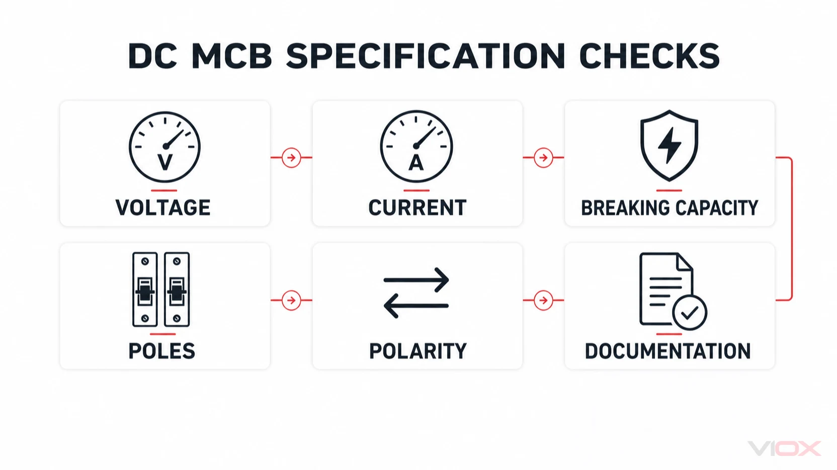
The initial specification review can be reduced to six linked checks:

Six DC MCB specification checks covering voltage, current, breaking capacity, poles, polarity, and documentation
  1. Voltage: Establish the circuit's maximum expected DC voltage using the project's applicable method.
  2. Current: Establish the circuit design current and the required conductor-protection coordination.
  3. Breaking capacity: Determine prospective fault current at the actual installation location.
  4. Poles: Confirm the documented arrangement required by the system and applicable installation rules.
  5. Polarity: Check source direction, device marking, and the manufacturer's exact connection diagram.
  6. Evidence: Confirm the relevant product standard, market requirements, operating conditions, and controlled technical documentation.

This checklist identifies the information a designer must gather; it is not a universal sizing procedure or permission to energize an unverified configuration. For a wider equipment-level comparison, continue to how to select circuit protection for a solar DC system.

VIOX DC MCB Product Families

VIOX publishes several modular DC circuit-breaker families that provide useful starting points for model evaluation. The figures below are published family-level ceilings, not a promise that every pole arrangement carries the same rating.

Product familySeries current ceilingSeries DC voltage ceilingVerification before specification
VOB3-63DCUp to 63 AUp to 1000 V DCConfirm exact pole configuration, DC interruption rating, trip characteristic, and installation diagram.
VOB6-63DCUp to 63 AUp to 1200 V DCConfirm exact configuration voltage, application conditions, connection instructions, and required market evidence.
VOB2-125DCUp to 125 AUp to 1000 V DCConfirm selected model current, configuration voltage, fault capability, terminals, and enclosure conditions.

The manufacturer describes these families as polarity-free, but that description does not override their actual controlled wiring instructions. Likewise, a published family voltage ceiling does not establish a given one-pole, two-pole, or four-pole configuration's permissible voltage.

Continue Your DC Protection Research

Use the DC circuit-breaker article archive for related technical resources, the solar DC circuit-protection guide for cross-device system decisions, and the PV combiner-box selection guide for assembly-level coordination.

When the required circuit, voltage, current, fault level, and market are defined, review the VIOX DC circuit-breaker product range and request the controlled documentation for the exact intended configuration at sales@vioxsolar.com.

Selection & Sizing

How to Select Circuit Protection for a Solar DC System

A practical input-to-specification workflow for coordinating fuses, DC breakers, SPDs, isolators, combiner boxes and rapid shutdown in PV DC circuits.
Solar DC protection architecture from PV strings through the inverter
VIOX / TECHNICAL ARTICLE
On this page

Solar DC protection should be selected from the circuit conditions—not from the system voltage printed on a product label. Start with the PV module data, inverter input architecture, number of parallel strings, expected environmental conditions, and destination-market rules. Then assign each required function to a specific circuit location before comparing device ratings.

The practical output is a device-location schedule: what must be protected or isolated, where the function belongs, which electrical ratings apply, and what evidence must accompany the selected device.

This guide supports preliminary design and procurement. Final calculations, coordination, installation, and approval must be completed by qualified personnel using the applicable edition of local regulations and project documents.

1. Freeze the system architecture first

A protective device cannot be evaluated correctly without knowing the circuit around it. Begin with the approved or proposed single-line diagram and mark these boundaries:

  • Each PV string and any group of parallel strings
  • Each inverter MPPT or DC input
  • Any array or sub-array combining point
  • Long DC cable runs and building entry points
  • DC/DC converters, optimizers, or rapid-shutdown equipment
  • Battery-connected DC circuits, if present
  • Accessible isolation points required for operation or maintenance

Do not assume that all strings should be combined into one output. Separate MPPT inputs may need electrically distinct groups. Some inverters already incorporate switching, surge protection, or string inputs; other architectures place those functions in an external PV combiner box.

IEC 62548-1 covers PV-array design requirements including DC wiring, electrical protection, switching, and earthing provisions. Its scope helps define the array-side design boundary, but the applicable edition and local adoption still need to be confirmed for the project.

2. Build the source-data worksheet

Use current, controlled documents. A copied value from an old quotation is not a reliable design input.

InputSourceWhy it matters
Module open-circuit voltage (Voc)Module datasheetStarting point for maximum circuit voltage
Module Voc temperature coefficientModule datasheetUsed with the project's minimum cell-temperature method
Module short-circuit current (Isc)Module datasheetStarting point for conductor and protection analysis
Module maximum series-fuse ratingModule datasheetUpper coordination boundary for string protection
Modules per stringString scheduleDetermines string voltage
Parallel strings per circuitSingle-line diagramAffects combined current and reverse-current exposure
Inverter maximum DC voltageInverter datasheetMust not be exceeded by corrected array voltage
MPPT voltage/current limitsInverter datasheetControls valid string grouping and input allocation
Inverter short-circuit contribution or backfeed dataInverter documentationNeeded for fault and interruption review
Minimum/maximum design temperaturesProject environmental dataAffects voltage, current-carrying ability, and equipment suitability
Installation locationLayout and site dataDefines enclosure, UV, water, dust, condensation, altitude, and access needs
Destination marketProject specificationDetermines adopted codes, standards, certification, and rapid-shutdown rules

If any critical field is unknown, record it as unresolved. Do not conceal the gap by selecting a larger nominal rating.

3. Establish the maximum DC voltage

The highest PV voltage commonly occurs when modules are cold. Determine the corrected maximum circuit voltage using the project-approved method, the module Voc temperature behavior, the number of modules in series, and the applicable design rules.

Then check that the complete current path is suitable for that voltage—not only the breaker or fuse. The review can include:

  • Inverter or power-conversion input
  • Fuse link and fuse holder
  • Circuit breaker pole arrangement
  • Switch-disconnector or isolator
  • SPD maximum continuous operating voltage for PV use
  • Connectors, terminals, cable, glands, and internal wiring
  • Combiner enclosure clearances and insulation design

A component marked “1000 V DC” is not automatically suitable for every 1000 V PV circuit. DC ratings can depend on pole configuration, polarity, utilization category, earthing arrangement, and the product standard under which the device was evaluated.

4. Determine current and reverse-current exposure

PV source circuits behave differently from conventional AC branch circuits. For each location, document:

  1. Expected operating current
  2. Module or string short-circuit current
  3. Number of parallel sources able to feed a fault
  4. Possible contribution from the inverter, converter, or battery
  5. Conductor current-carrying capacity after installation corrections
  6. Maximum current allowed by terminals, connectors, and other components

The need for string overcurrent protection depends on the potential fault current and the module's permitted reverse-current or maximum series-fuse boundary. It is not determined by string count alone. The applicable PV-array design rules must be used to decide whether protection is required and which conductors or poles must be protected.

Where PV fuse links are selected, verify the intended photovoltaic fuse class and the complete fuse system—not only the ampere value. IEC 60269-6 addresses supplementary requirements for fuse-links used to protect solar PV systems. The holder, temperature conditions, time-current behavior, breaking capacity, and coordination with the module and conductor all remain part of the selection.

5. Assign one clear function to each device

Protection designs become confusing when device names are treated as interchangeable. Define the required function first.

FunctionTypical device familyKey verification questions
String overcurrent protectionPV DC fuse or suitable DC protective deviceIs protection required? Is it coordinated with module reverse current, conductor, holder, and fault level?
Overload/short-circuit protection and switchingDC circuit breakerAre DC voltage, poles, polarity, breaking capacity, trip behavior, and isolation suitability documented?
Surge limitationPV DC SPDIs it intended for PV DC? Are Ucpv, protection mode, Type, In/Imax or Iimp, Up, backup protection, and earthing path suitable?
Operational or maintenance isolationDC isolator switchIs the utilization category suitable for the load? Are all required live conductors switched? Is the location accessible and identifiable?
String combining and enclosurePV combiner boxDoes the box preserve MPPT groups and integrate the required protection, isolation, terminals, and environment rating?
Module-level or array-level shutdownRapid shutdown deviceIs it required in the destination market? What initiation, controlled-conductor, voltage, timing, and compatibility rules apply?

A circuit breaker may provide both protection and switching, but it should only be called an isolating device when that function is explicitly supported by its standard, markings, and documentation. Likewise, an isolator is not automatically an overcurrent protective device.

Solar DC protection device location map for strings, combiner output and inverter input

6. Choose between a fuse and a DC circuit breaker

The correct question is not “Which is better?” It is “Which device can perform the required function at this location with documented coordination?”

Comparison of PV fuses and DC circuit breakers by function and selection input

A PV fuse is often considered when:

  • Compact string-level protection is required
  • A photovoltaic fuse class is specified
  • The fuse characteristic can be coordinated with the module, conductor, holder, and prospective fault current
  • Replacement after operation is acceptable and controlled

A DC circuit breaker is often considered when:

  • Resettable overcurrent protection is required
  • The breaker provides a suitable switching or isolation function
  • Its DC voltage, pole arrangement, polarity conditions, breaking capacity, and trip characteristic fit the circuit
  • The device can be coordinated with upstream and downstream protection

IEC 60947-2 covers circuit breakers within its scope, while IEC 60947-3 covers switches, disconnectors, switch-disconnectors, and fuse-combination units. Referencing one of these standards does not replace verification of the exact product rating and PV application.

7. Select the PV DC surge protection function

An SPD is selected from the lightning and surge-risk design, earthing arrangement, equipment withstand level, conductor routing, and applicable installation rules. Avoid selecting it from nominal array voltage alone.

At minimum, record:

  • SPD type required by the risk and protection concept
  • PV maximum continuous operating voltage (Ucpv)
  • Protection modes and connection arrangement
  • Nominal and maximum discharge-current ratings, or impulse-current rating where applicable
  • Voltage protection level (Up)
  • Short-circuit behavior and any required backup protection
  • Status indication and optional remote signaling
  • Lead routing and earthing requirements for the final installation design

IEC 61643-31 addresses requirements and test methods for SPDs intended for the DC side of photovoltaic installations. The project still needs an installation-level decision about SPD type, location, coordination, and local code requirements.

8. Verify isolation and shutdown boundaries

Isolation supports safe operation and maintenance; rapid shutdown addresses a separate, market-dependent function. Do not merge the two requirements in an RFQ.

For each isolating point, specify:

  • Circuit and location
  • Maximum voltage and current
  • Required number of switched poles
  • Load-breaking duty or utilization category
  • Locking, position indication, and accessibility requirements
  • Enclosure and environmental conditions
  • Coordination with inverter-integrated switching

For rapid shutdown, identify the destination jurisdiction and exact governing requirement before selecting equipment. The initiation method, controlled conductor boundary, permitted voltage, time requirement, communication method, and equipment compatibility can be region-specific.

9. Check interruption, coordination, and the complete assembly

The device's interrupting or breaking capacity must be suitable for the prospective fault current at its installation point. A PV array may have limited source current, but a connected battery, converter, parallel array, or other source can materially change the available fault energy.

Coordination review should cover:

  • Protective device versus conductor withstand
  • String device versus module maximum series-fuse rating
  • Upstream versus downstream selectivity where required
  • SPD short-circuit behavior and backup protection
  • Breaker or switch DC pole arrangement
  • Fuse link and holder compatibility
  • Terminal and connector current/temperature limits
  • Enclosure thermal performance with all devices installed

The assembly matters. A list of individually rated components does not by itself prove the completed box meets the project requirement.

10. Include the environment and service conditions

Record whether equipment is indoors, outdoors, shaded, exposed to direct sun, installed at altitude, subject to condensation, salt, dust, vibration, or restricted ventilation. Confirm:

  • Permitted ambient-temperature range and any derating
  • Enclosure ingress-protection requirement
  • UV and corrosion resistance where relevant
  • Cable-entry direction and gland range
  • Heat dissipation and spacing
  • Mounting orientation and access
  • Labels, circuit identification, and service clearances

An enclosure rating describes specific tested ingress conditions; it does not by itself establish suitability for every outdoor environment.

11. Example: turn project inputs into a preliminary schedule

Assume a project has multiple PV strings allocated across separate inverter MPPT inputs. The design team has supplied module and inverter datasheets, corrected maximum voltage, circuit-current results, a lightning/surge assessment, and the rooftop environmental specification.

The preliminary schedule should not jump directly to a product model. It should look like this:

LocationRequired functionPreliminary specificationStill to verify
Each protected stringOvercurrent protectionPV-rated fuse system or documented DC protective device, coordinated with module and conductorFinal rating, time-current coordination, holder temperature
Each MPPT groupCombiningInputs and outputs matching the approved MPPT groupingInternal conductor and terminal schedule
Array-side surge pointSurge limitationPV DC SPD with project-defined Type, Ucpv, modes, discharge rating, and UpRisk assessment, backup protection, lead arrangement
Combiner outputSwitching/isolationDC switch-disconnector or suitable breaker for corrected voltage/current and required polesUtilization category and isolation documentation
Outdoor assemblyEnvironmental protectionEnclosure matched to ingress, UV, corrosion, temperature, and entry requirementsThermal verification and mounting details
Required shutdown boundaryRapid shutdownMarket-specific equipment architectureJurisdiction, inverter compatibility, initiation method

This format exposes missing inputs before procurement and prevents a nominal-voltage match from being mistaken for a complete design.

12. Solar DC protection RFQ checklist

Send these items with an RFQ:

  • Current module and inverter datasheets
  • Approved or proposed single-line diagram
  • String schedule: modules per string, parallel strings, and MPPT allocation
  • Corrected maximum voltage calculation and design temperatures
  • Circuit-current and reverse-current analysis
  • Prospective fault-current information from every possible source
  • Required fuse, breaker, SPD, isolation, and shutdown functions by location
  • Cable sizes, entry ranges, and conductor material
  • Enclosure, ambient, altitude, UV, corrosion, and mounting requirements
  • Destination country and applicable code/standard editions
  • Required drawings, test records, certificates, labels, and inspection documents
  • Monitoring, auxiliary contacts, or remote-signaling requirements

VIOX can review the requested configuration across DC breakers, PV fuses, SPDs, isolators, combiner boxes, connectors, and rapid-shutdown devices. Send the source documents and unresolved fields to sales@vioxsolar.com; final approval remains with the project's qualified designer and authority having jurisdiction.

Frequently asked questions

Is system voltage enough to select a DC breaker?

No. Check corrected maximum voltage, pole arrangement, polarity conditions, rated current, breaking capacity, trip behavior, circuit conductors, environment, and the intended protection or isolation function.

Does every parallel PV string need a fuse?

Not automatically. The decision depends on possible reverse current, the number and arrangement of parallel sources, module limits, conductor protection, and applicable design rules.

Can an SPD replace overcurrent protection?

No. An SPD limits transient overvoltage. It does not perform the same function as a fuse or circuit breaker.

Is a DC isolator the same as a DC circuit breaker?

No. An isolator or switch-disconnector provides a switching/isolation function within its documented ratings. A circuit breaker provides overcurrent protection and may also be suitable for switching or isolation when explicitly rated for those functions.

Which standards should appear in the specification?

List the installation and product standards actually applicable to the destination market and design. For an IEC-oriented project, the review may include IEC 62548-1 and IEC 60364-7-712 at installation level, plus product-scope checks such as IEC 60269-6, IEC 60947-2, IEC 60947-3, and IEC 61643-31. Confirm current editions and local adoption.

Sources and further reading

Fundamentals & Technology

What Is a PV Combiner Box and What Does It Do?

A clear guide to the system boundary, functions, components and decision paths of photovoltaic combiner boxes.
PV combiner box as the collection point between multiple solar strings and an inverter
VIOX / TECHNICAL ARTICLE
On this page

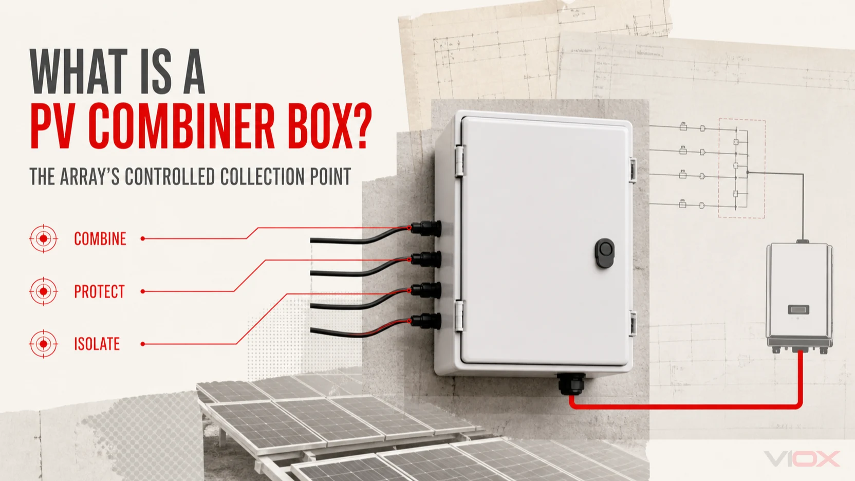
A PV combiner box is an electrical assembly that receives multiple photovoltaic source circuits and organizes them into one or more output circuits before the inverter or other power-conversion equipment. Depending on the project, it can also provide string overcurrent protection, surge protection, output isolation, monitoring, terminals, and a protected enclosure.

The word “combiner” describes its basic circuit role. It does not mean every combiner box contains the same devices—or that every PV system needs a separate box.

Where a PV combiner box sits in the system

A simplified string-inverter path may be shown as:

PV modules → PV string → combiner box → inverter DC input → AC system

Several strings enter the box on separate input circuits. Inside the assembly, conductors are terminated and arranged according to the approved single-line diagram. One or more output circuits then continue toward the inverter.

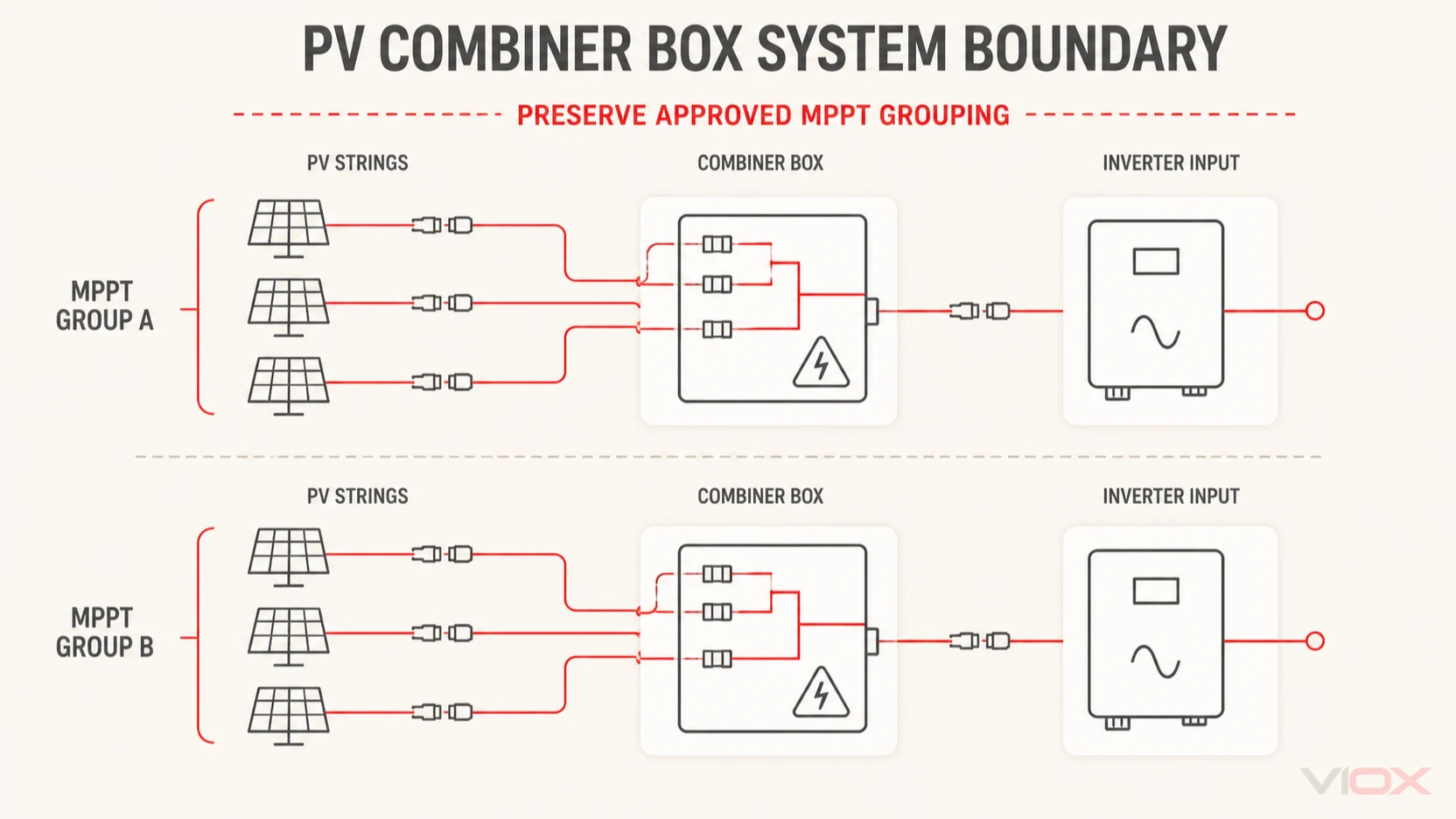
This boundary is important. Strings assigned to different maximum power point tracker (MPPT) inputs should not be combined merely to reduce the number of cables. The box must preserve the electrical grouping required by the inverter design.

Modern inverters sometimes accept individual string inputs and incorporate functions that once required an external combiner. In those systems, a separate box may be unnecessary or may serve only a limited collection, protection, or transition role.

PV combiner box system boundary preserving independent inverter MPPT groups

What does a solar combiner box do?

1. Organizes PV source circuits

The box provides defined entries, terminals, circuit identification, and output routing. This can simplify cable collection between an array area and the inverter, especially where multiple strings share the same approved electrical group.

2. Provides string overcurrent protection when required

Parallel strings can feed current back into a faulted string. Where the design rules and module limits require overcurrent protection, a box may contain PV DC fuse links and holders or another documented DC protection arrangement.

Protection is not selected from string count alone. The designer must evaluate possible reverse current, module maximum series-fuse rating, conductor limits, temperature, fault contribution, and the applicable installation rules.

3. Limits transient overvoltage

A combiner box can contain a PV DC surge protective device. The SPD is chosen for the PV DC circuit and the project's surge-protection concept, including its maximum continuous operating voltage, type, protection modes, discharge-current capability, voltage protection level, backup protection, and earthing path.

An SPD does not protect against sustained overload or short circuit in the same way as a fuse or breaker.

4. Creates a switching or isolation point

An output DC isolator switch or a suitably documented DC circuit breaker may provide a local switching point. The required function must be stated clearly: load switching, maintenance isolation, overcurrent protection, or a combination supported by the device ratings.

5. Supports monitoring and maintenance

Larger or project-specific assemblies may include string-current monitoring, auxiliary contacts, SPD remote indication, communications, or other status functions. These features can improve visibility, but they do not replace commissioning measurements or a maintenance plan.

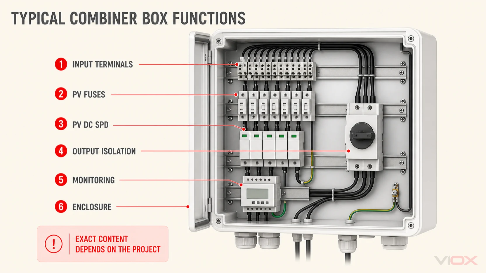
Typical components inside a PV combiner box

ComponentPossible purposeWhat must be project-defined
Input terminals or connectorsReceive string circuitsQuantity, conductor range, polarity, temperature, compatibility
PV fuse links and holdersString overcurrent protectionNeed, rating, class, breaking capacity, coordination, temperature
Busbars or distribution conductorsCombine currentCurrent, material, insulation, spacing, thermal performance
PV DC SPDLimit transient overvoltageType, Ucpv, modes, discharge ratings, Up, backup protection
Switch-disconnector or DC breakerOutput switching/isolation and possibly protectionVoltage, current, poles, utilization category, breaking capacity, function
Monitoring moduleMeasure or signal circuit statusChannels, accuracy, supply, protocol, alarms
Earthing/PE terminalProvide protective and SPD connection pointsConductor arrangement and installation design
Enclosure and cable glandsProtect and organize the assemblyIngress, UV, corrosion, impact, temperature, condensation, cable sizes

“Fully equipped” is not a technical specification. A useful purchase description identifies the required function and rating of each part.

Typical PV combiner box components including terminals, fuses, SPD and output isolation

Combiner box, junction box, and inverter: what is the difference?

PV combiner box versus a junction box

A junction box is a broad term for an enclosure containing electrical connections. A PV combiner box is defined by its array-circuit role: accepting multiple PV source circuits and arranging them into output circuits, often with protection or isolation functions.

PV combiner box versus an inverter

The inverter converts DC power into AC power. A combiner box does not perform that conversion. It sits on the DC collection side and may prepare, protect, isolate, or monitor circuits before they reach the inverter.

PV combiner box versus a rapid-shutdown device

A rapid shutdown device performs a market-specific shutdown function. A combiner box may interact with such an architecture, but ordinary output isolation at a combiner does not automatically satisfy rapid-shutdown requirements.

When is a separate PV combiner box useful?

A separate combiner is often evaluated when:

  • Multiple strings need to be collected into defined output circuits
  • String overcurrent protection is required outside the inverter
  • The surge-protection concept places an SPD near the array collection point
  • A local switching or isolation point is required
  • Long cable routes benefit from structured collection and circuit identification
  • String monitoring or remote status is specified
  • A project needs a controlled transition between field cables and outgoing feeders

It may not be needed when an inverter already accepts the strings individually and provides the required project functions, or when the array architecture has too few strings to justify an external assembly. The decision should follow the single-line diagram, inverter instructions, and applicable rules.

Common combiner-box arrangements

The input/output notation commonly used in model names can describe physical circuit arrangements, but it should not be confused with a complete electrical specification.

  • 1-in/1-out: A protected or isolated transition for one source circuit
  • 2-in/1-out: Two compatible input circuits combined into one output
  • 2-in/2-out: Two input circuits remain as two controlled output circuits
  • 3-in/1-out or 3-in/3-out: Three inputs are combined or retained as independent outputs according to the design
  • Higher string-count assemblies: Multiple strings grouped into one or more outputs, often with string fusing and optional monitoring

Before choosing any arrangement, confirm which strings belong to each inverter MPPT and whether the current and protection design permits them to share an output.

The VIOX PV combiner box range includes 600 V and 1000 V product configurations with several small input/output arrangements. These are product-family options, not a substitute for project-specific voltage, current, protection, and environmental checks.

How to tell whether a specification is complete

A useful combiner-box specification answers all of the following:

  1. How many strings enter, and how are they assigned to MPPTs?
  2. What is the corrected maximum DC voltage?
  3. What are string Isc, operating current, and possible reverse current?
  4. Is string overcurrent protection required, and how is it coordinated?
  5. What output current and number of output circuits are required?
  6. What surge-protection type and ratings follow from the project design?
  7. Is output isolation, load switching, or breaker protection required?
  8. What enclosure, ambient, UV, corrosion, condensation, and cable-entry conditions apply?
  9. Is monitoring or remote indication needed?
  10. Which drawings, test records, certificates, and labels are required for the destination market?

If these inputs are not yet known, use the PV combiner box selection guide to build a quote-ready schedule. For the wider protection architecture, read How to Select Circuit Protection for a Solar DC System.

Standards and compliance boundaries

No single standard reference proves every aspect of a combiner-box project. Separate layers can apply to:

  • PV-array design and installation
  • Low-voltage assembly construction
  • Individual fuse, breaker, switch, and SPD products
  • Enclosure and ingress performance
  • Destination-market certification and inspection

IEC 62548-1 addresses PV array design requirements, including DC wiring, electrical protection devices, switching, and earthing provisions. Product-specific standards may then apply to fuses, circuit breakers, switches, and PV SPDs. The exact editions, local adoption, assembly requirements, and certification scheme must be stated in the project specification.

A certificate or standard logo should be matched to the exact manufacturer, model, rating, and scope. Generic component certificates do not automatically certify a completed assembly.

Frequently asked questions

Does every solar system need a combiner box?

No. The need depends on string count, inverter input architecture, required protection and isolation functions, cable layout, monitoring, and local rules.

Is a combiner box the same as a DC distribution box?

The terms can overlap in practice, but “PV combiner box” specifically describes the collection of PV source circuits. Always define inputs, outputs, and functions rather than relying on the label.

Does a combiner box increase power?

No. It organizes circuits and may provide protection, switching, surge limitation, or monitoring. It does not create electrical energy.

Can strings connected to different MPPTs share one combiner output?

They generally should not be combined across MPPT boundaries unless the inverter and system design explicitly provide for that arrangement. Follow the approved single-line diagram and inverter requirements.

Can I select a combiner box only by voltage and string count?

No. Current, reverse-current exposure, output arrangement, device ratings, enclosure conditions, monitoring, cable entries, standards, and documentation also matter.

Next step

For a project-specific review, send the module and inverter datasheets, string schedule, single-line diagram, corrected maximum voltage, current analysis, installation environment, and destination market to sales@vioxsolar.com.

Sources and further reading

Selection & Sizing

How to Select a PV Combiner Box

A step-by-step workflow for converting PV string and inverter data into a complete combiner box specification and RFQ.
PV combiner box selection pathway from topology and electrical data to a quote-ready RFQ
VIOX / TECHNICAL ARTICLE
On this page

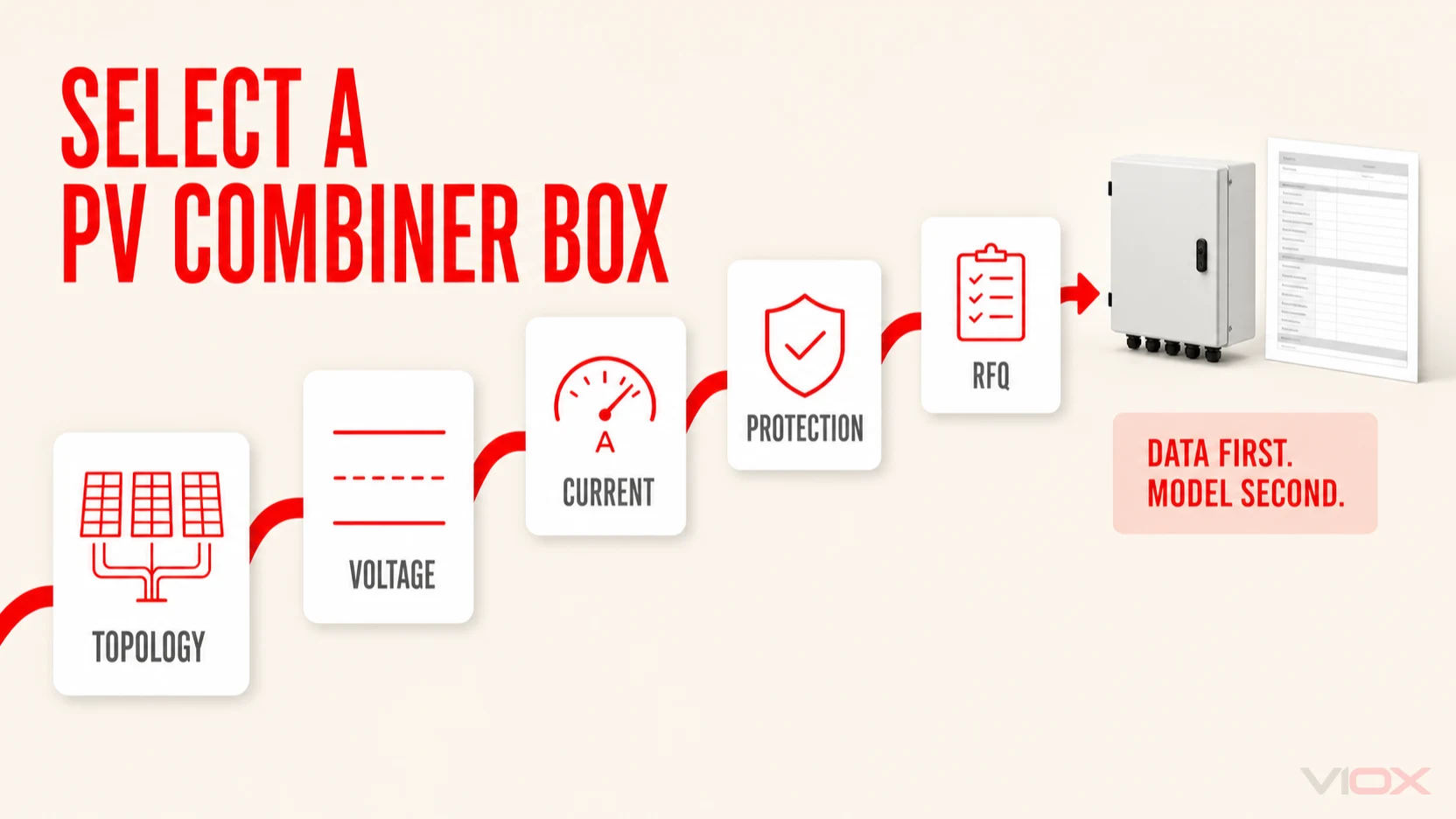
Select a PV combiner box by converting the approved array and inverter design into a circuit-by-circuit specification. The minimum inputs are MPPT grouping, string count, corrected maximum DC voltage, string current and reverse-current exposure, required protection and isolation functions, output arrangement, installation environment, and destination-market documentation.

Do not select a box from “1000 V” and “number of strings” alone. Those two labels cannot confirm current capacity, protection coordination, SPD suitability, switching duty, enclosure performance, or inverter compatibility.

This workflow supports preliminary specification and procurement. Final calculations, protection coordination, assembly verification, and installation must be completed by qualified personnel under the applicable project rules.

If you first need the system role and component boundary, read What Is a PV Combiner Box and What Does It Do?. For coordination across the complete DC path, use the solar DC circuit-protection selection workflow.

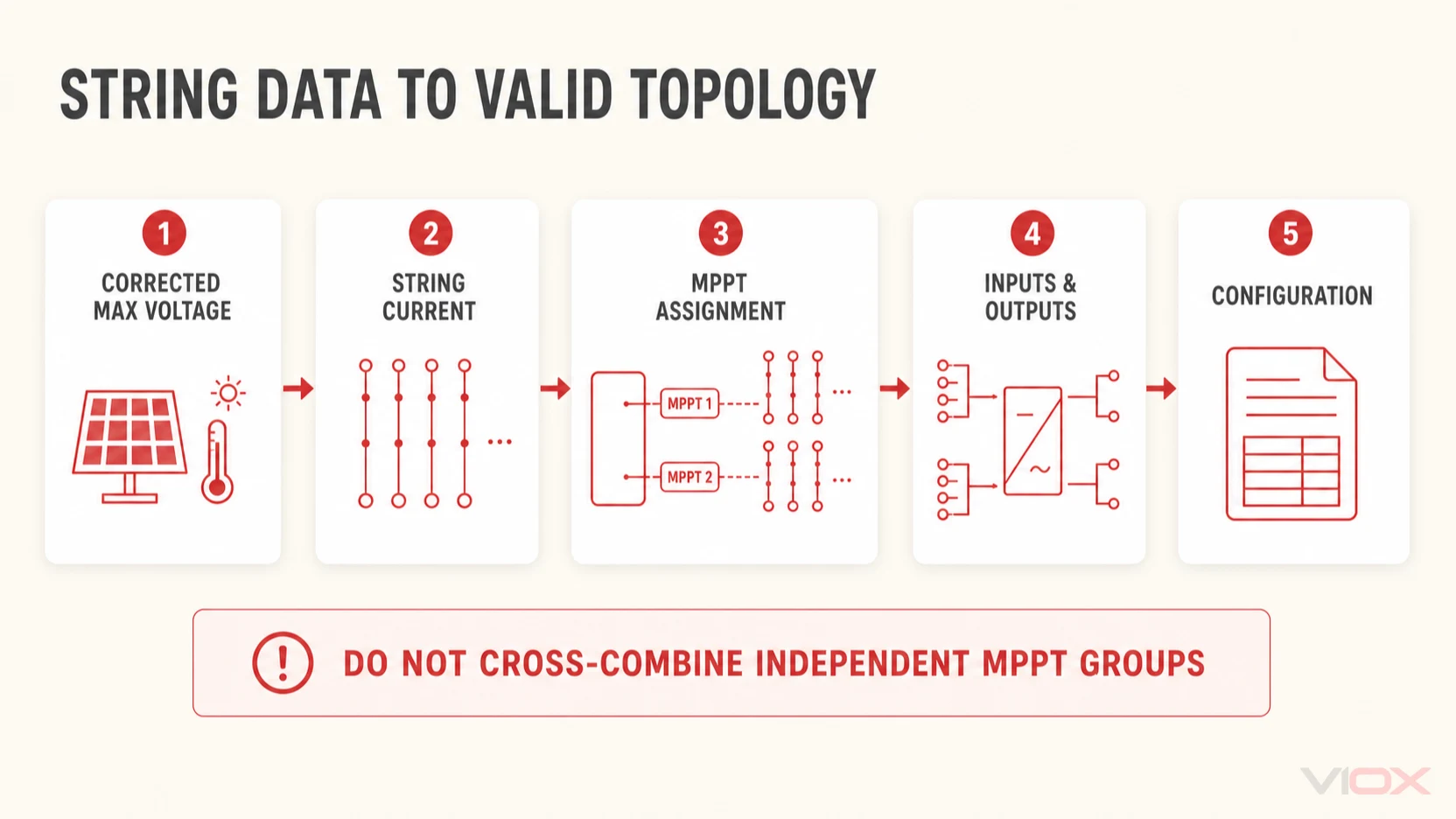
Stage 1: Freeze the topology and string schedule

Confirm the inverter and MPPT topology

Start with the single-line diagram and inverter datasheet. Record:

  • Number of inverter DC inputs and MPPTs
  • Permitted strings per input
  • Maximum DC input voltage
  • MPPT operating-voltage range
  • Maximum operating and short-circuit current per input
  • Whether inputs are internally commoned or electrically independent
  • Integrated fuse, SPD, switch, or monitoring functions

Allocate every string to an MPPT before defining combiner outputs. Strings facing different orientations, using different module counts, or assigned to separate trackers may need to remain in separate electrical groups.

The number of physical inputs on a box does not authorize strings to be combined. The inverter architecture controls the grouping.

Complete the string schedule

Create one row for every string or identical string group.

FieldWhat to record
String IDUnique project label
Module manufacturer and modelExact controlled datasheet reference
Modules in seriesCount per string
Module Voc and coefficientDatasheet values used by the project calculation
Corrected maximum string voltageApproved result for minimum design temperature
Module IscDatasheet source-current value
Design current resultValue calculated under the applicable method
Maximum series-fuse ratingModule coordination boundary
MPPT assignmentInverter input group
Cable size and typeInput conductor and gland requirement

If strings are not electrically identical, do not collapse them into one generic row. Differences in module type, series count, orientation, or tracker assignment can change the valid combining arrangement.

Five-step flow from corrected PV string data through MPPT assignment to combiner configuration

Stage 2: Set voltage, current, and protection requirements

Set the combiner voltage requirement

Use the corrected maximum string voltage—not the nominal system label. The corrected result should follow the module temperature data, minimum design temperature, series-module count, and project-approved code method.

Verify voltage suitability across the complete assembly:

  • Input terminals or connectors
  • Fuse links and fuse holders
  • Internal conductors and busbars
  • SPD Ucpv and connection arrangement
  • Output switch-disconnector or breaker
  • Output terminals and cable glands
  • Insulation, spacing, and assembly construction

The selected equipment rating must exceed or equal the required design value under the applicable rules, but adding an arbitrary “safety factor” is not a substitute for the required calculation.

The currently documented VIOX PV combiner box range covers 600 V and 1000 V classes in small 1-in/1-out through 3-in/3-out arrangements. These independent input/output arrangements are not automatically equivalent to an N-in/1-out box that combines several parallel strings onto one output. Confirm the required topology before treating voltage class or input count as a product match.

Determine string protection requirements

Evaluate the current that can flow into a faulted string from all parallel sources and any other connected equipment. Compare that exposure with:

  • Module reverse-current limits or maximum series-fuse rating
  • Input conductor current-carrying capacity
  • Connector and terminal ratings
  • Applicable PV-array design rules
  • Prospective fault current and required breaking capacity

Where string fuses are required, specify a photovoltaic fuse system and verify both link and holder. The schedule should include:

  • Fuse class/application
  • Rated voltage
  • Rated current
  • Breaking capacity
  • Time-current coordination
  • Holder voltage/current rating
  • Temperature and enclosure conditions
  • Replacement and labeling requirements

IEC 60269-6 covers supplementary requirements for fuse-links used to protect PV systems. It does not remove the need to coordinate the exact PV DC fuse with the module, conductor, holder, and fault conditions.

Do not replace a specified fuse with a larger rating because of nuisance operation until the cause has been investigated. Incorrect class, temperature, loose connections, damaged wiring, reverse-current exposure, or a real fault can all require different corrective action.

Calculate the output-circuit requirements

For each combiner output, record the number of contributing strings and the project-calculated current. Then verify:

  • Busbar and internal conductor capacity
  • Output terminal and connector capacity
  • Outgoing cable current-carrying capacity
  • Output device continuous-current rating and any derating
  • Prospective fault current from every connected source
  • Inverter input-current and short-circuit-current limits

If a box has multiple outputs, document which inputs feed each output. A “3-in/3-out” arrangement can serve a very different task from “3-in/1-out.” Input/output notation describes topology, not protection completeness.

Stage 3: Specify surge protection and the output device

Define the surge-protection specification

The SPD requirement comes from the project's lightning and surge-risk design, conductor routing, earthing system, equipment withstand level, and applicable rules. For a PV DC SPD, state at least:

  • Required SPD type
  • Maximum continuous operating voltage for PV (Ucpv)
  • Protection modes and pole arrangement
  • Nominal discharge current (In)
  • Maximum discharge current (Imax), or impulse current (Iimp) where relevant
  • Voltage protection level (Up)
  • Short-circuit behavior and backup-protection requirement
  • Local status indication and remote contact, if required
  • Replaceable cartridge requirement, if required

IEC 61643-31 provides requirements and test methods for SPDs intended for the DC side of PV installations. The selection still needs installation-level coordination. A generic “Type 2 SPD included” description is incomplete without voltage, mode, discharge, protection-level, and short-circuit data.

See the VIOX PV DC SPD family for available product categories, then verify the exact model against the completed schedule.

Define output switching, isolation, or breaker protection

State the required function instead of asking only for “a DC switch.” Possible requirements include:

  • Operational switching
  • Maintenance isolation
  • Overcurrent and short-circuit protection
  • Lockable OFF position
  • Visible or reliable position indication
  • Remote auxiliary status

For a DC isolator switch, verify voltage, current, number of poles, wiring arrangement, DC utilization category, operating duty, and isolation markings. For a DC circuit breaker, also verify breaking capacity and trip behavior.

IEC 60947-3 covers switches, disconnectors, switch-disconnectors, and fuse-combination units within its scope. IEC 60947-2 covers circuit breakers within its scope. A standard reference must be tied to the exact model and rating; it should not be used as a generic compliance shortcut for the finished assembly.

Stage 4: Match the enclosure and connections to the site

Select the enclosure from the site conditions

“Outdoor” is not enough information. Record:

  • Minimum and maximum ambient temperature
  • Direct solar exposure and UV conditions
  • Rain, dust, washdown, and condensation exposure
  • Salt, ammonia, chemical, or corrosion conditions
  • Altitude
  • Impact and vandalism risk
  • Mounting surface and orientation
  • Required ingress-protection level
  • Enclosure material and corrosion treatment
  • Cable-entry direction, quantity, and gland ranges
  • Drain, vent, or pressure-equalization requirements where engineered
  • Service access and clearance

Check thermal performance with all protective devices operating inside the enclosure. Component current ratings may change with ambient temperature, grouping, and heat dissipation.

An IP code is one part of the enclosure specification. It does not by itself establish UV resistance, corrosion resistance, condensation control, or long-term suitability for a particular site.

Specify terminals, cables, and connectors

Record conductor material, size range, insulation type, temperature rating, and termination method for every input and output. Confirm that:

  • Terminals accept the specified conductor
  • Cable glands match outside diameters and maintain enclosure protection
  • Positive and negative circuits are clearly identified
  • Bending space is adequate
  • Protective-earthing points are defined
  • Field connectors are compatible as a complete connection system

Mating connectors from different manufacturers merely because they share a familiar form factor can create compatibility and certification problems. Use documented, compatible connector pairs and the specified tooling. See the VIOX MC4 solar connector product family for project options.

Stage 5: Define monitoring and controlled documents

Decide whether monitoring is required

Monitoring can be simple or extensive. Define the actual output needed:

  • Individual string current or grouped current
  • Fuse status
  • SPD status and remote alarm
  • Isolator or breaker auxiliary position
  • Enclosure temperature
  • Door status
  • Communication protocol and address scheme
  • Auxiliary supply voltage
  • Local display or remote-only reporting

Confirm how monitoring channels map to string labels and how data will integrate with the plant supervisory system. “Monitoring included” is not a testable requirement.

Define documentation and verification

Include required deliverables in the RFQ, not after production. Depending on the project, request:

  • General arrangement drawing
  • Single-line and internal wiring diagrams
  • Bill of materials with exact manufacturer/model references
  • Terminal and cable-entry schedule
  • Device datasheets
  • Applicable certificates matched to exact models and ratings
  • Routine inspection or test records
  • Torque schedule
  • Labels and nameplate artwork
  • Packaging and spare-parts list
  • Change-control and document-revision requirements

Separate component evidence from assembly evidence. A certificate for a fuse or SPD proves only the scope stated on that certificate; it does not automatically cover the complete box.

Stage 6: Build and review the RFQ

Illustrative PV combiner box RFQ structure

Consider a hypothetical rooftop project with several strings divided across two independent inverter MPPTs. The design team wants one outdoor assembly near the array, but the MPPT groups must remain separate.

The quote request should define the architecture in fields rather than asking for a generic “multi-string box”:

RFQ fieldIllustrative entry
Electrical topologyTwo independent input groups; no cross-combining between MPPTs
Inputs/outputsState exact string inputs and one output per approved group
Maximum voltageProject-calculated corrected value; supplier device ratings to be verified above this requirement
String currentDatasheet Isc and approved design-current result attached
String protectionRequired/not required based on reverse-current analysis; exact fuse coordination attached
Surge protectionProject-defined PV DC SPD Type, Ucpv, modes, In/Imax or Iimp, Up, and backup protection
Output deviceDefined as isolation, load switching, breaker protection, or approved combination
EnvironmentOutdoor conditions, temperature range, UV/corrosion exposure, ingress requirement, mounting
Cable entriesInput/output conductor sizes and outside diameters
MonitoringExact channels, contacts, protocol, and auxiliary supply—or “not required”
EvidenceDrawings, BOM, device datasheets, matched certificates, and routine-test record

This example intentionally omits numeric ratings. Those values must come from the project's module, inverter, environmental, and engineering calculations—not from a reusable article.

Reject these incomplete selection shortcuts

  • “Choose a 1000 V box for a 1000 V system.” The corrected maximum voltage and every component rating still need verification.
  • “Use one fuse size for all modules.” Module current, maximum series-fuse rating, conductor, holder, and design rules vary.
  • “Every outdoor box should be IP65.” The site environment and all enclosure performance needs must be specified.
  • “All strings can share one output.” MPPT grouping and inverter current limits may prohibit it.
  • “Type 2 SPD” is a complete SPD specification. Ucpv, modes, discharge ratings, Up, short-circuit behavior, and coordination are still missing.
  • “The component certificates certify the whole box.” Component and assembly evidence have different scopes.

Final PV combiner box RFQ checklist

Quote-ready PV combiner box RFQ framework covering electrical, protection and enclosure requirements

Before requesting a quotation, attach:

  • Module datasheet and inverter datasheet
  • Approved or proposed single-line diagram
  • String schedule and MPPT allocation
  • Corrected maximum string-voltage calculation
  • Design current and reverse-current analysis
  • Required input/output topology
  • String protection decision and coordination data
  • SPD selection fields
  • Output switching/isolation/protection function
  • Input and output cable schedule
  • Environmental and enclosure requirements
  • Monitoring and auxiliary requirements
  • Destination country and applicable standards/certification scheme
  • Drawing, test, labeling, packaging, and spare-parts requirements

Send the completed schedule to sales@vioxsolar.com for a VIOX configuration discussion. Any proposed model or assembly should then be reviewed against the project's controlled documents by the responsible engineer.

Frequently asked questions

How many strings can a combiner box handle?

The physical input count varies by model, but the acceptable electrical grouping depends on MPPT architecture, current, protection, terminals, internal conductors, and output ratings.

Should a PV combiner box use fuses or breakers?

Choose from the required function and coordination study. PV fuses are common for compact string protection; suitable DC breakers can provide resettable protection and switching. Neither is automatically correct for every location.

What voltage rating should I choose?

Use the project-calculated maximum voltage under the lowest design temperature and verify every series component, pole arrangement, and assembly insulation requirement against that value.

Is monitoring necessary?

Not for every project. It is more valuable where individual string visibility, remote fault indication, or plant-level data integration is required. Specify exact channels and outputs.

Can the supplier calculate everything from module wattage?

No. Module wattage alone does not establish Voc temperature behavior, Isc, series-fuse limit, string length, parallel-source exposure, MPPT grouping, or site requirements.

Sources and further reading

PROJECT INQUIRY

Tell us what you need.

Share your product, project or OEM requirements. Our sales team will review the details and follow up with the next practical step.

Products · Projects · OEM / ODM
Email
sales@vioxsolar.com
Support
Selection, quotation and OEM

Project files can be shared during sales follow-up.

By submitting, you acknowledge our Privacy Policy and Terms of Service.

Search VIOX products & resources