Skip to content

Applications & Use Cases

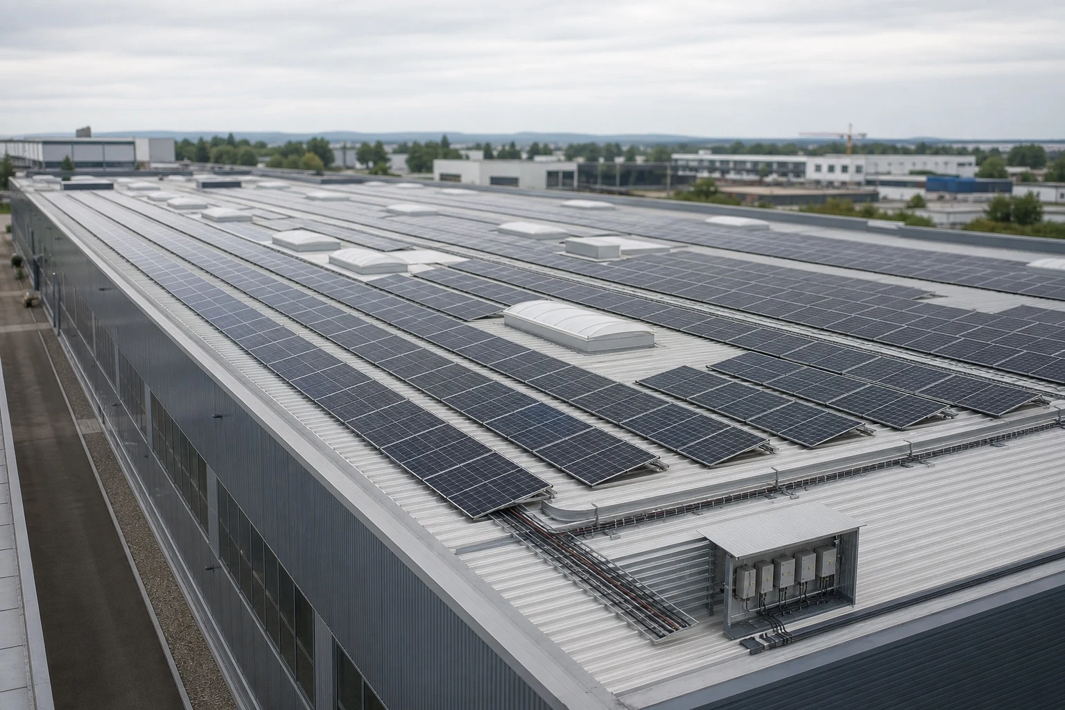
PV Combiner Boxes for Commercial Rooftop Systems

How combiner-box configuration changes for rooftop zones, long cable routes and multiple inverter inputs.
PV Combiner Boxes for Commercial Rooftop Systems article cover
VIOX / TECHNICAL ARTICLE
On this page

How combiner-box configuration changes for rooftop zones, long cable routes and multiple inverter inputs.

1. Coordinate the roof layout

Group strings according to inverter MPPT design, roof zones and cable-routing constraints. Clear labeling reduces commissioning and maintenance errors.

2. Plan for the environment

Review temperature, UV exposure, water entry, condensation, mounting location and service access before specifying enclosure material and IP protection.

3. Request project guidance

Send the string data, single-line diagram, installation environment and target market to sales@vioxsolar.com for a project-specific discussion.

Maintenance & Troubleshooting

PV Combiner Box Installation and Troubleshooting Checklist

A compact field checklist for polarity, torque, cable entry, fuse failures and SPD status.
PV Combiner Box Installation and Troubleshooting Checklist article cover
VIOX / TECHNICAL ARTICLE
On this page

A compact field checklist for polarity, torque, cable entry, fuse failures and SPD status.

1. Installation checks

Verify string polarity, conductor preparation, terminal torque, gland sealing, protective earthing, fuse compatibility and circuit labels before energization.

2. When a fuse keeps opening

Do not simply install a larger fuse. Check reverse-current exposure, string faults, wiring damage, fuse class, temperature conditions and coordination with the module maximum series fuse rating.

3. Request project guidance

Send the string data, single-line diagram, installation environment and target market to sales@vioxsolar.com for a project-specific discussion.

Standards, Testing & Compliance

PV Combiner Box Standards and Compliance Basics

A practical IEC standards crosswalk for PV combiner boxes, explaining assembly, array, component, enclosure, and supplier-evidence boundaries.
PV combiner box standards and compliance document framework
VIOX / TECHNICAL ARTICLE
On this page

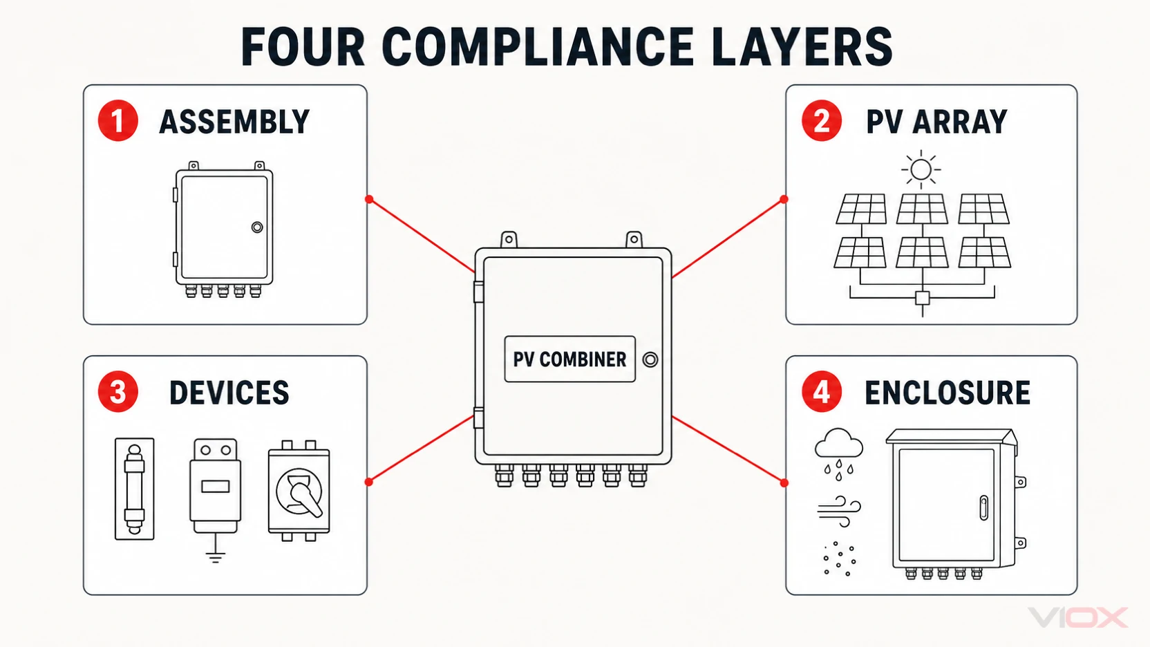
There is no single component certificate that establishes compliance for a complete photovoltaic (PV) combiner box. A defensible compliance package normally has four layers: the assembled switchgear enclosure, the PV-array application, the standards for each incorporated protective device, and the destination market's project requirements. The correct question is therefore not “Which one standard applies?” but “Which requirement applies to each layer, and what evidence proves it?”

This guide provides that scope map. It does not declare that every standard below applies to every project, and it does not claim certification for a particular VIOX product. The contract, national adoption, equipment architecture, rated values, and authority requirements determine the final list.

The four compliance layers

A combiner box is both an assembly and part of a PV array. Its fuse-links, surge protective devices (SPDs), breakers or switch-disconnectors may each have their own product standards, while the enclosure and completed assembly require separate evidence.

Compliance layerMain questionTypical evidenceWhat it does not prove by itself
Complete assemblyWas the finished combiner designed and verified as an assembly for its declared ratings and service conditions?Assembly standard declaration, design-verification evidence, routine-verification record, rating label, drawingsThat every installation decision is correct for the project
PV-array applicationDoes the architecture satisfy the array's wiring, protection, switching, and earthing requirements?Approved single-line diagram, array calculations, project specification, installation design reviewProduct certification of the assembled combiner
Incorporated devicesAre fuse-links, SPDs, breakers, and switch-disconnectors suitable for their assigned functions and DC conditions?Exact datasheets, certificates where required, coordination records, device markingsCompliance of the complete enclosure or assembly
Enclosure and environmentDoes the enclosure protect against the declared ingress and service conditions?IP evidence, enclosure documentation, material and environmental data, thermal assessmentUniversal outdoor suitability, corrosion resistance, UV life, or condensation control
Four compliance layers for a PV combiner box: assembly, PV array, incorporated devices, and enclosure evidence

The distinction matters in procurement. A certified fuse-link inside an enclosure does not automatically validate conductor sizing, temperature rise, clearances, terminals, protective bonding, short-circuit withstand, or the finished assembly's declared ratings.

IEC standards scope crosswalk

The following table is a planning crosswalk based on the official IEC publication scopes. Confirm the adopted edition and any national deviations in the destination market before putting a dated standard into a purchase order.

StandardRelevant scope for a PV combiner boxEvidence to requestImportant boundary
IEC 61439-1:2020 with IEC 61439-2:2020General rules and specific requirements for power switchgear and controlgear assemblies up to 1,500 V DC; Part 2 includes photovoltaic-installation annexesDeclared assembly ratings, applicable design-verification evidence, routine-verification record, drawings, bill of materialsPart 1 is used with the relevant assembly part; a component certificate is not an assembly verification
IEC 62548-1:2023PV-array design requirements, including DC array wiring, electrical protection, switching, and earthing provisionsApproved array design inputs, string and MPPT arrangement, protection concept, switching and earthing decisionsIt is an array-design standard, not a product certificate for the combiner assembly
IEC 60269-6Supplementary requirements for fuse-links protecting PV strings and arrays in circuits up to 1,500 V DCExact fuse-link class, rated values, time-current data, breaking-capacity evidence, holder coordinationIt covers PV fuse-links; it does not validate the complete box, holder installation, or conductor system
IEC 61643-31:2018Requirements and test methods for SPDs connected to the DC side of PV installations up to 1,500 V DCExact SPD datasheet, declared ratings, test or certification evidence where specified, backup-protection conditionsIt addresses the SPD product; it does not complete the project's SPD selection or placement decision
IEC 61643-32:2017Selection, installation, and coordination principles for SPDs in PV systemsRisk and location basis, Ucpv and protection-level selection, connection-mode and coordination recordApplication guidance does not itself certify the SPD or the finished assembly
IEC 60947-2:2024Circuit-breakers for circuits up to 1,500 V DC within the standard's scopeExact breaker ratings, breaking capacity, isolation suitability when required, pole and polarity documentationA breaker cannot be treated as a switch-disconnector or PV string protector without documented suitability
IEC 60947-3:2020Switches, disconnectors, switch-disconnectors, and fuse-combination units up to 1,500 V DCUtilization category, rated operational voltage and current, isolation documentation, conditional short-circuit conditionsA disconnector's isolation function is not the same as overcurrent protection
IEC 60529Classification of ingress protection provided by enclosuresDeclared IP code and the supporting test or enclosure evidenceIP classification does not alone prove UV, corrosion, condensation, chemical, or thermal suitability
IEC 62208:2023General requirements and tests for empty enclosures used as part of switchgear and controlgear assembliesEnclosure construction and test documentation appropriate to indoor or outdoor useEmpty-enclosure evidence does not replace verification of the populated assembly

The standards serve different evidence objects. IEC 61439 addresses the completed assembly framework; IEC 62548-1 addresses the PV-array design context; the IEC 60269, 61643, and 60947 series address incorporated devices; IEC 60529 and IEC 62208 support enclosure claims.

What assembly verification should establish

For a combiner treated as a low-voltage power switchgear and controlgear assembly, the supplier's file should connect the declared configuration to the applicable assembly requirements. The exact verification route depends on the standard and design, but the record should be traceable to the supplied product rather than to a generic catalogue image.

The evidence package should identify at least:

  • the assembly manufacturer and exact configuration;
  • rated operational voltage, current, and other declared assembly characteristics;
  • applicable service conditions and enclosure arrangement;
  • incorporated-device identities and their coordination conditions;
  • conductor, terminal, protective-bonding, and insulation arrangements;
  • the basis used for temperature-rise and short-circuit-related verification where applicable;
  • design-verification evidence applicable to the configuration;
  • routine-verification results for the manufactured unit;
  • markings, drawings, and document revisions delivered with the product.

This is why replacing one fuse, SPD, switch, terminal, enclosure, or conductor with an apparently similar part can require an engineering review. The substitution may change a characteristic that was part of the verified assembly design.

Component conformity is not assembly conformity

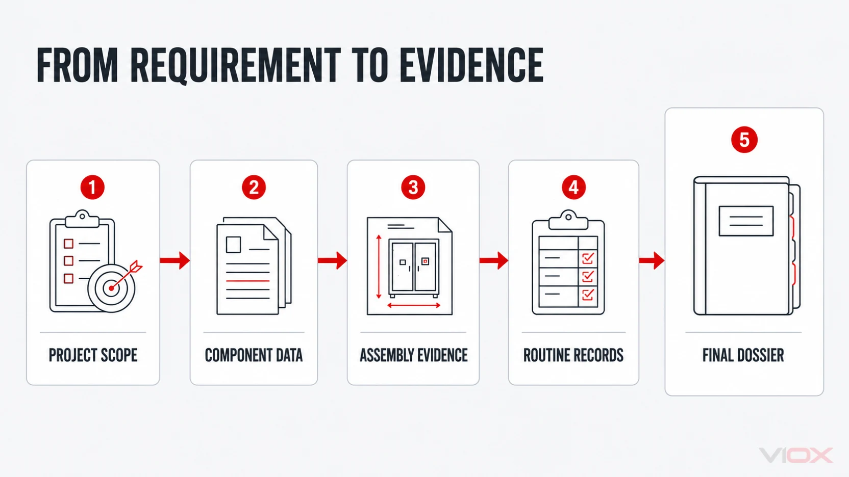
Procurement files often contain several valid component documents but no clear statement about the completed combiner. Keep the evidence chain explicit:

  1. The project specification defines the destination market, electrical architecture, service conditions, and required deliverables.
  2. The component documents establish the characteristics and conformity evidence of the exact incorporated devices.
  3. The assembly record explains how those devices are integrated and how the finished design addresses the relevant assembly requirements.
  4. Routine records identify checks performed on the manufactured unit.
  5. The final dossier ties markings, drawings, bill of materials, certificates, and revisions to the delivered configuration.
Evidence chain from project requirements and component documents to assembly verification and the final combiner-box dossier

For example, PV fuse-link requirements and DC breaker requirements describe different protective-device evidence. Neither device family alone proves the suitability of the complete combiner.

Supplier document package

An RFQ should ask for controlled, configuration-specific evidence instead of a broad request for “all certificates.” The following matrix is a practical starting point.

Document or recordWhat it should identifyWhy it mattersReview point
Compliance matrixEach contractual requirement, applicable standard, edition, and evidence referencePrevents standards from being listed without a matching deliverableConfirm national adoption and exclusions
General arrangement and single-line diagramInputs, outputs, protective devices, switching, terminals, earthing, and cable entriesConnects the electrical function to the physical assemblyMatch the approved project architecture
Bill of materialsExact manufacturer and model of safety-relevant componentsMakes component evidence traceable and controls substitutionsRequire revision and change-control status
Component evidenceDatasheets and required certificates for fuse-links, holders, SPDs, switches, breakers, terminals, and enclosureConfirms the assigned product characteristicsCheck ratings, DC suitability, and conditions of use
Assembly design-verification fileEvidence applicable to the declared assembly design and configurationSupports the completed assembly claimCheck configuration and rating boundaries
Routine-verification recordUnit-specific inspection and verification resultsShows the manufactured unit was checked before releaseTie the record to serial or batch identity
Rating label and marking scheduleDeclared ratings, identification, warnings, and circuit labelsAllows the delivered product to be matched to its dossierCompare against drawings and quotation
Installation and maintenance informationPermitted conditions, handling, inspection, replacement, and service boundariesPreserves the assumptions behind the product and assembly evidenceUse only controlled manufacturer instructions

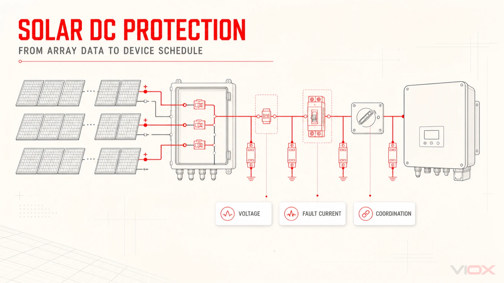
The list is intentionally evidence-focused. Final device selection still begins with corrected array voltage, current, parallel-source behavior, MPPT grouping, prospective fault conditions, and environmental inputs. Those decisions belong in the PV combiner box selection workflow, not in a standards title.

How to state the requirement in an RFQ

A clear compliance clause should be specific enough to review but flexible enough to reflect the destination market. Include these elements:

  1. Market and authority basis: destination country, required national adoption, certification scheme, authority having jurisdiction, and contract edition.
  2. Assembly boundary: input and output arrangement, system voltage, current duties, earthing concept, enclosure location, and service conditions.
  3. Applicable standards: the assembly, array-design, component, and enclosure standards that actually correspond to the architecture.
  4. Evidence deliverables: compliance matrix, exact component documents, drawings, bill of materials, design-verification evidence, routine records, and markings.
  5. Deviation process: a written method for declaring exclusions, alternative standards, substitutions, and evidence limitations before production.

Avoid clauses such as “IEC compliant” without a standard number, edition, scope, and deliverable. Also avoid requiring every standard found in a generic list: an irrelevant requirement adds paperwork without improving technical assurance.

Common compliance interpretation errors

Treating an IP rating as complete outdoor suitability

An IP code classifies protection against defined access and ingress conditions. Outdoor suitability may also depend on UV exposure, corrosion, condensation, temperature, mounting, drainage, seals, cable glands, and maintenance. Record these separately.

Using a device certificate as evidence for the finished box

Device evidence remains important, but the assembly introduces terminals, conductors, heat sources, spacing, protective bonding, enclosure effects, and coordination conditions. Request both component and assembly evidence.

Omitting editions and national adoption

Standards change, and national or contractual requirements may adopt a particular edition with modifications. Record the edition at the project level and confirm it before ordering—not by copying a date from an unrelated certificate.

Assuming one architecture fits every market

PV-array protection, switching, earthing, surge protection, and certification rules depend on the system and jurisdiction. Keep IEC product and design scopes separate from national installation rules and approval schemes.

Accepting an untraceable document bundle

A certificate or test record has limited procurement value when it cannot be tied to the exact model, bill of materials, rating, revision, or supplied configuration. Traceability is part of the evidence review.

Applying the crosswalk to a VIOX project

The VIOX PV combiner box family provides a starting route for configured photovoltaic combining, protection, surge protection, and DC isolation. The controlled datasheet and approved quotation define the supplied product; this article does not replace those documents or declare a certification scope.

Before requesting a quotation, prepare the target market, approved single-line diagram, corrected string voltage, string and MPPT arrangement, environmental conditions, required standards and editions, and evidence-delivery list. For system context, start with what a PV combiner box does and the broader solar DC protection workflow.

Send the project inputs and document requirements to sales@vioxsolar.com for a configuration-specific review.

Selection & Sizing

MCB vs MCCB vs RCCB vs RCBO: Complete Selection Guide

Understand what each protective device actually protects, calculate a preliminary feeder current, compare trip characteristics, and avoid specification mistakes.
MCB vs MCCB vs RCCB vs RCBO: Complete Selection Guide article cover
VIOX / TECHNICAL ARTICLE
On this page

MCBs, MCCBs, RCCBs and RCBOs may sit beside one another in a distribution system, but they do not perform the same job. Correct selection begins by separating three risks: overload, short circuit and earth-leakage current.

The calculations and curves below are illustrative design aids. Final selection must use the exact manufacturer data, installation method, conductor rating, prospective fault current, applicable standard and local code.

1. The four devices in one minute

An MCB is a compact miniature circuit breaker normally used for final circuits and smaller feeders. It protects conductors against overload and short circuit. An MCCB provides the same broad overcurrent functions at higher currents and fault levels, often with adjustable trip settings and additional accessories.

An RCCB monitors the imbalance between outgoing and returning current. It disconnects when residual current exceeds its threshold, helping protect against electric shock and fire caused by earth leakage. It does not, by itself, provide overload or short-circuit protection. An RCBO combines residual-current protection and overcurrent protection in one device.

Compact final-circuit protection.

Feeders, incomers and adjustable protection.

Leakage protection; requires coordinated OCPD.

Residual current plus overload and short circuit.

2. Compare functions before comparing ratings

The quickest way to make a wrong selection is to compare only the ampere value printed on the front. A 63 A RCCB and a 63 A MCB describe different functions. The RCCB current marking indicates the current it can carry under stated conditions; it does not turn the RCCB into a 63 A overload protective device.

Device — Overload — Short circuit — Earth leakage — Typical role

MCB — Yes — Yes — No — Final circuits, small feeders

MCCB — Yes — Yes — Optional by release — Distribution, machinery, incomers

RCCB — No — No — Yes — Group residual-current protection

RCBO — Yes — Yes — Yes — Individual final circuits

3. Calculate the load current first

For a balanced three-phase load, a useful preliminary relationship is:

Here, P is active power in watts, V is line-to-line voltage, PF is power factor and η is efficiency. The calculator adds a configurable design factor and identifies the next standard rating for early comparison.

Interactive engineering tool

Three-phase feeder current calculator

Estimate operating and design current before verifying cable ampacity, fault level, starting current and protective-device settings.

VIOX / CALC 02
Preliminary protection reference125 A

Next standard rating at or above the calculated design current. This is not a final breaker selection.

Calculated load current
82.1 A
Factored design current
102.6 A
Reference frame
MCCB

Do not select the breaker from this result alone. Confirm that the protective device rating and settings coordinate with the conductor current-carrying capacity. Motor starting current, transformer inrush, harmonics, grouping, enclosure temperature and altitude can materially change the decision.

4. How B, C and D curves change MCB behavior

The curve letter does not describe product quality. It identifies the instantaneous magnetic operating range. A B-curve device responds at a lower current multiple than a C- or D-curve device, while the thermal overload region remains governed by the applicable product characteristic.

Interactive engineering curve

Illustrative B, C and D time-current comparison

Move the current slider to compare estimated response time for three normalized 32 A examples.

Selected current160 A
100.11101001k10kProspective current (A)Illustrative operating time (s)

Normalized educational points shown to test the interactive article layout.

Do not use these illustrative lines for protection coordination or product claims. Use the controlled curve for the exact VIOX model, pole configuration, rating and test standard.

  • B curve: often considered for resistive or low-inrush circuits after coordination checks.
  • C curve: commonly considered where moderate inrush is expected.
  • D curve: intended for higher inrush applications only when conductor protection and fault-loop conditions remain satisfactory.

5. When an MCCB becomes the better platform

The transition from MCB to MCCB is not defined by one universal current value. MCCBs become relevant when the circuit needs a larger frame size, higher breaking capacity, adjustable long-time or instantaneous settings, selective coordination, shunt trips, undervoltage releases, auxiliary contacts or communications.

An MCCB is not simply a larger MCB. Its value is the ability to coordinate a distribution system with adjustable protection, higher fault-duty capability and system-level accessories.

For an incomer, verify rated operational voltage, frame size, rated current or plug setting, ultimate and service breaking capacities, trip-unit technology, neutral arrangement, utilization category, isolation suitability and environmental derating.

6. RCCB type and sensitivity matter

Residual-current waveforms are no longer always sinusoidal. Electronic power supplies, variable-speed drives, photovoltaic inverters, EV charging equipment and other converters can introduce pulsating DC or higher-frequency components. The RCCB or RCBO type must match the expected residual-current waveform.

Type — Responds to — Typical consideration

AC — Sinusoidal residual AC — Use only where permitted and appropriate for the load

A — AC plus pulsating DC — Many modern single-phase electronic loads

F — Type A waveforms plus defined mixed frequencies — Selected single-phase variable-frequency equipment

B — AC, pulsating and smooth DC within stated scope — Applications with potential smooth DC residual current

Sensitivity is equally important. A 30 mA device is commonly associated with additional protection against electric shock, while higher thresholds may be used for fire protection or upstream selectivity where standards permit. Never increase the threshold merely to hide unexplained leakage or nuisance tripping.

7. RCBO or RCCB plus MCB?

An RCBO isolates only the affected final circuit, improving fault localization and continuity. A shared RCCB feeding several MCBs can reduce device count, but one leakage event may disconnect the entire group and accumulated standing leakage must be considered.

  1. Use individual RCBOs where circuit continuity and fault identification are priorities.
  2. Consider grouped RCCB protection only after assessing simultaneous leakage, discrimination and the consequences of losing every downstream circuit.
  3. Confirm switched poles, neutral arrangement and line/load orientation for the exact device.

8. Breaking capacity and prospective fault current

The breaker must interrupt the prospective short-circuit current at its installation point. A load calculation cannot provide this value. Fault current depends on the source, transformer impedance, conductor impedance and network arrangement. Compare the calculated or declared prospective current with the device breaking-capacity definition under the relevant standard.

MCB and MCCB standards may express breaking performance using different symbols and test sequences. Do not treat Icn, Icu and Ics as interchangeable values.

9. A practical selection workflow

  1. Define system voltage, frequency, phases, earthing arrangement and load type.
  2. Calculate design current and document continuous load, diversity and starting behavior.
  3. Select and derate the conductor for installation method, grouping and ambient conditions.
  4. Determine prospective fault current at the installation point.
  5. Choose overload and short-circuit protection that coordinates with the conductor.
  6. Decide whether residual-current protection is required and select its type, sensitivity and time delay.
  7. Check selectivity with upstream and downstream devices.
  8. Confirm isolation, pole switching, accessories, enclosure and environmental ratings.
  9. Validate against the exact manufacturer datasheet and applicable standards.

10. Worked example: 45 kW three-phase motor feeder

Assume a 45 kW motor at 400 V, power factor 0.86 and efficiency 0.92. The preliminary full-load current is approximately 79.4 A. Applying a 1.25 design factor produces about 99.3 A. This points toward a 100 A reference frame, but the final solution still depends on the starting method and verified motor data.

A fixed C-curve 100 A device should not be assumed suitable. The engineer must compare starting current and duration with the exact time-current characteristic, confirm conductor withstand and calculate the minimum fault current needed for timely operation. An adjustable MCCB or coordinated motor-protection solution may provide a better fit.

11. Common specification mistakes

  • Using an RCCB as though it provides overload protection.
  • Selecting breaker current before selecting and derating the conductor.
  • Choosing a D curve solely to stop nuisance tripping.
  • Ignoring DC components in residual current.
  • Comparing breaking-capacity numbers from different standards without definitions.
  • Installing multiple electronic loads behind one 30 mA RCCB without checking accumulated leakage.
  • Assuming two devices with the same current rating have interchangeable curves.

12. Final checklist for procurement

A useful request for quotation should state the device function, poles, rated current, system voltage, frequency or DC duty, trip curve or adjustable settings, breaking capacity, residual-current type and sensitivity where applicable, installation environment, accessories, certifications and expected annual quantity.

For help matching a VIOX protection platform to your application, send the single-line diagram, load schedule and fault-level information to sales@vioxsolar.com.

PROJECT INQUIRY

Tell us what you need.

Share your product, project or OEM requirements. Our sales team will review the details and follow up with the next practical step.

Products · Projects · OEM / ODM
Email
sales@vioxsolar.com
Support
Selection, quotation and OEM

Project files can be shared during sales follow-up.

By submitting, you acknowledge our Privacy Policy and Terms of Service.

Search VIOX products & resources