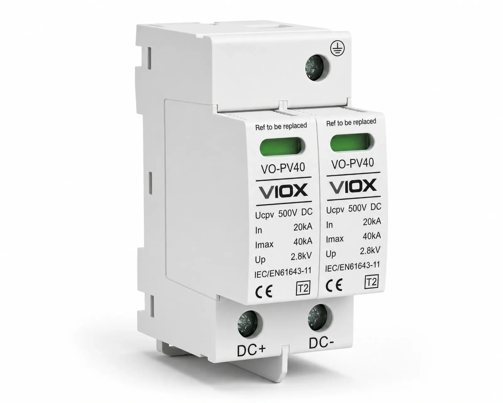
VO-PV40 Series VO-PV40 PV DC Surge Protective Device Type 2 photovoltaic DC surge protection for combiner boxes, inverters and DC distribution cabinets.
500 / 600 / 800 / 1000 / 1200 / 1500 V DC Maximum continuous operating voltage (Ucp)
20 kA Nominal discharge current (In)
40 kA Maximum discharge current (Imax)
<25 ns Response time
01 / PRODUCT VIEW 01 / PRODUCT OVERVIEW VO-PV40 photovoltaic DC surge protective device VO-PV40 is a modular Type 2 PV DC surge protective device based on high-energy varistors. The range provides 500V to 1500V DC maximum continuous operating voltage references, a 20kA nominal discharge current, a 40kA maximum discharge current and a listed response time below 25ns.
02 / TECHNICAL DATA
VO-PV40 technical data Use these values for initial selection. Confirm the PV array voltage, voltage protection level, protected mode, earthing arrangement, conductor size and controlled documentation before ordering.
Electrical, installation and environmental specifications Maximum continuous operating voltage (Ucp) 500 / 600 / 800 / 1000 / 1200 / 1500 V DC
Nominal discharge current (In) 20 kA
Maximum discharge current (Imax) 40 kA
Response time <25 ns
Voltage protection level (Up) 2.8 / 3.2 / 3.5 / 3.8 / 4.5 / 5 kV
Protected mode DC+ to PE / DC- to PE
Protection grade IP20
Internal component High-energy varistor
Shell material PBT / PA66
Failure indication Visual status indicator
Ambient temperature -40°C to +80°C
Installation 35mm standard DIN rail
Power-line conductor 16–35 mm² multicore flexible cable
Zero-line conductor 2.5–35 mm²
Minimum grounding conductor >6 mm² multi-strand copper wire
Maximum grounding lead length ≤500 mm
Remote signal function Optional
Supplied standards reference GB 18802.1 / GB 50057 / IEC 61643-1
Product label standard IEC/EN 61643-11
Show all specifications (+9) VO-PV40 installation dimensions Dimension drawing Request the current dimension drawing for this model.
Maximum continuous operating voltage — Select against corrected maximum PV array voltage Maximum continuous operating voltage Select against corrected maximum PV array voltage
500 V DC / Up 2.8 kV 600 V DC / Up 3.2 kV 800 V DC / Up 3.5 kV 1000 V DC / Up 3.8 kV 1200 V DC / Up 4.5 kV 1500 V DC / Up 5 kV
Module arrangement — Confirm the protected circuit configuration Module arrangement Confirm the protected circuit configuration
2 modules / 36 mm width 3 modules / 54 mm width
Remote signal — Optional monitoring function Remote signal Optional monitoring function
Without remote signal With remote signal
04 / APPLICATIONS
Applications for VO-PV40 PV combiner boxes Protect photovoltaic string-combining equipment against transient overvoltage.
PV inverter DC inputs Provide coordinated DC-side surge protection ahead of photovoltaic inverter input circuits.
Solar DC distribution Install on a 35mm DIN rail in DC distribution cabinets and photovoltaic control equipment.
05 / RESOURCES VO-PV40 controlled documents Request documents matched to the selected voltage, module arrangement and destination market.
VO-PV40 technical datasheet Request the controlled ratings and voltage-reference table. Request Document VO-PV40 dimension drawing Request the current 2-module or 3-module installation drawing. Request Document VO-PV40 compliance documents Request documents applicable to the final reference and destination market. Request Document Which VO-PV40 voltage references are available? The supplied range lists 500V, 600V, 800V, 1000V, 1200V and 1500V DC maximum continuous operating voltage references.
What are the discharge current ratings? The listed nominal discharge current is 20kA and the maximum discharge current is 40kA.
Where is VO-PV40 installed? VO-PV40 mounts on a standard 35mm DIN rail in PV combiner boxes, inverter input equipment and DC distribution cabinets.
Is remote signaling available? Yes. A remote signal function is listed as an optional configuration.
READY FOR SELECTION?
Confirm VO-PV40 for your application. 
 01 / PRODUCT VIEW